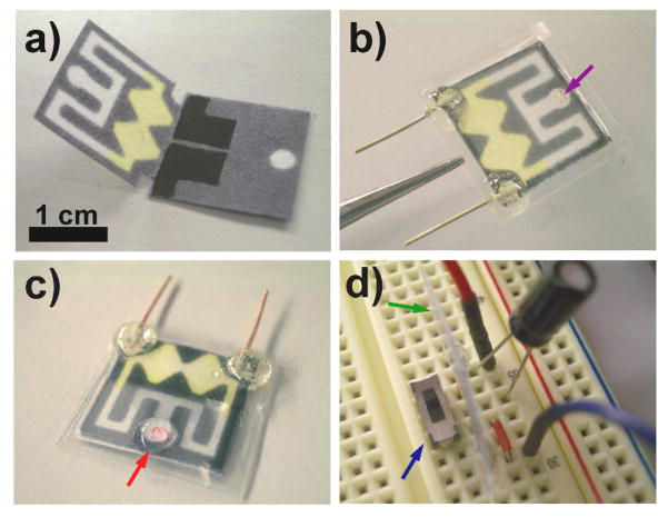
Figure 1.
a) A photograph of the unfolded oPAD fabricated by wax printing on chromatography paper. The two screen-printed carbon electrodes are visible on the bottom layer. The yellow color arises from the presence of Fe(CN)63− preloaded in the channel for the electrochemical assay. b) A photograph of the folded oPAD encapsulated in plastic using thermal edge lamination. The purple arrow indicates an opening for sample introduction, and the two copper wires are for electrical read-out. c) A photograph of the oPAD after introducing a 20 μL sample at the inlet (red arrow). The solution flows into the oPAD and splits into two channels. A movie showing this process is available in the Supporting Information. d) A photograph of a 2.2 μF capacitor, a switch (blue arrow), an oPAD (edge view, green arrow), and jumper wires on a breadboard for measuring the output current of the device using a DMM and simultaneously accumulating charge onto the capacitor.

