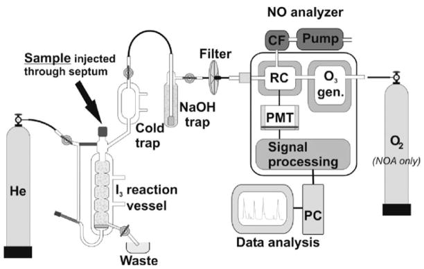
Fig. 4.3.
Chemiluminescence apparatus setup. Reaction vessel is filed with I3 solution with He carrier gas gently bubbling though. Sample is injected using Hamilton syringe through septum into I3 solution where NOx components are reduced to NO gas and carried into NO analyzer. Cold trap, NaOH-filled trap, and filter protect analyzer against humidity and acid vapors. In reaction chamber (RC) NO gas is combined with O3 (generated in O3 generator) from O2 either from O2 tank or from room air. Chemiluminescence signal from NO2* is detected by photomultiplier tube (PMT) and further amplified and processed. Data acquisition and analysis are carried out on PC. Vacuum pump created low pressure in the reaction chamber (RC) and evacuates toxic NO2 gas after chemiluminescence measurement through charcoal filter (CF).

