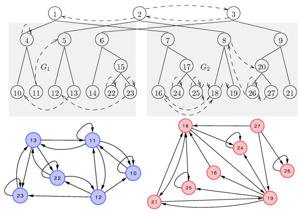
Figure 1.
Framework Overview. A duplication forest (solid edges at top) with the non-tree edges (dashed) necessary to construct G1 and G2 (shown at bottom). Nodes 1, 2, and 3 represent the 3 homology groups present in the ancestral graph. Node 14 was lost. As an example of the connectivity induced by the non-tree edges, consider edge (27,18) in G2 which is implied by the directed non-tree edge from (3,2). However, the reverse edge (18,27), which is implied by (2,3), does not exist because its state is flipped by (8,20).

