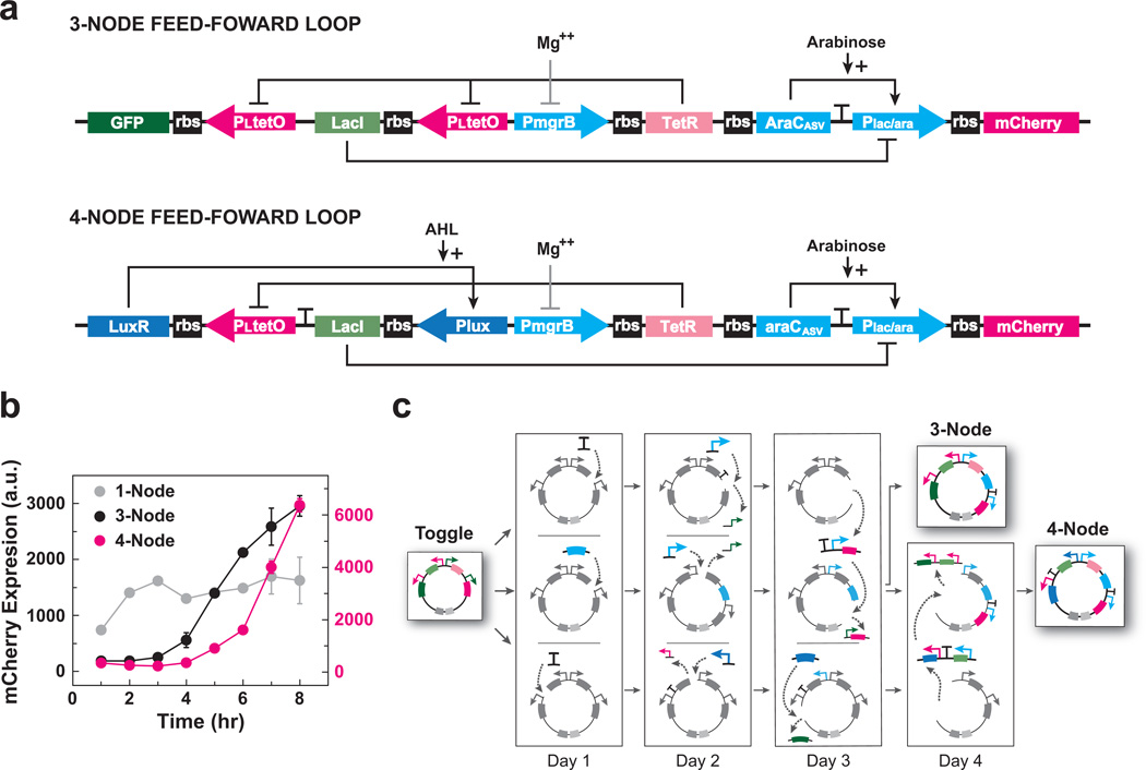
Figure 3.
Transformation of the genetic toggle switch into functional three- and four-node feed-forward loops. (a) Schematics of the three- and four-node feed-forward loop networks. Mg++ indirectly inhibits PmgrB via the PhoPQ two-component system. (b) Pulse response for one-, three- and four-node feed-forward loops. Cells containing the three- or four-node feed-forward loops were induced by the absence of MgCl2. After a 6 hour induction, MgCl2 was spiked into the media to stop induction. Flow cytometry measured mCherry fluorescence (a.u.) at one-hour intervals over an 8 hour time-course. Fluorescence data for one-node and three-node loops are plotted on the left (black) y-axis; fluorescence data for the four-node loop is plotted on the right (red) y-axis. Points represent mean values for three experiments ± s.d.; n = 10,000 events per experiment. (c) Representation of the five-day, parallel subcloning process used to construct plasmids encoding three- and four-node feed-forward loops starting from a genetic toggle switch.

