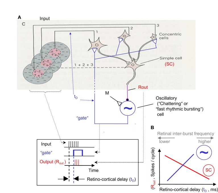
Figure 6.
NPLL implemented by a visual thalamocortical loop. (A) A schematic description of the proposed thalamocortical closed loop decoder. The scheme is based on the schematic description of the FF connectivity suggested by Hubel and Wiesel (1962); the feedback connectivity added in blue closes the loop in a way that permits a PLL-like operation. Excitatory and inhibitory connections are represented by open triangles and solid circles, respectively. Dashed line indicates possible poly synaptic link. Input, retinothalamic input; SC, simple cells; M, modulatory excitatory input; ∼, oscillatory (“chattering”) neurons. Inset: implementation of the phase detection function by corticothalamic gating: the output is active only when both the Input and the “gate” are active. (B) Schematic phase plane of the two basic transfer functions of the loop. SC’s transfer function (red): output spike count (Rout) decreases as the retino-cortical delay (tD) increases. Oscillatory cells transfer function (blue, dashed): tD increases as Rout increases (note reversal of axes here). The crossing point of the transfer functions is the set point for a specific retinal temporal frequency. The inter-burst frequency of the retinal input is directly related to tD and inversely related to Rout.

