
Figure 5. (Overleaf) PreBötC projections to ipsilateral BötC.
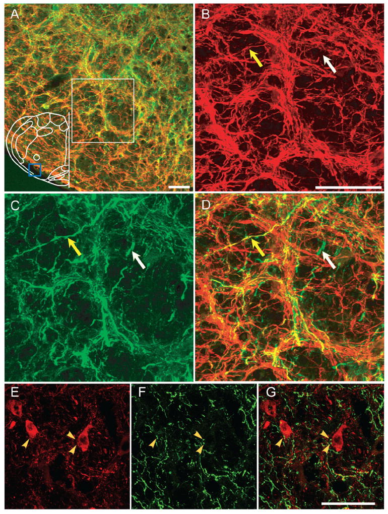
A: EGFP-expressing processes from unilaterally injection into preBötC project to ipsilateral BötC. Few EGFP processes (green) were MAP2-ir (red) (mainly in the most caudal portion of BötC). Blue box in outline represents area where images were acquired. B–D: Higher magnification of immunoreactivity for MAP2 (B), EGFP (C), and overlap (D) from the region in white box of (A) in ipsilateral BötC. White arrow indicates absence of colocalization between EGFP and MAP2, whereas yellow arrow indicates colocalization. E: PV-ir neurons (red) in BötC. F: EGFP-expressing processes (green) from unilateral injection projecting into BötC. G: Superimposition of (E) and (F), showing some EGFP processes in juxtaposition to PV-ir neurons in BötC. Yellow arrows indicate occurrence of direct contacts of EGFP-expressing processes on to PV BötC neurons. Magenta-green copy of this figure is available as Supporting Figure 5. Scale bars = 50 μm. [Color figure can be viewed in the online issue, which is available at www.interscience.wiley.com.]