
FIGURE 3.
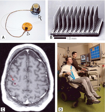
Intracortical microelectrode array and its placement in a patient with tetraplegia. A, The 100-microelectrode array on top of a US penny. B, The microelectrode array in a scanning electron micrograph. C, The preoperative axial T1-weighted magnetic resonance image of the patient. The red square in the precentral gyrus shows the approximate location of the array. D, The patient sitting in a wheelchair and working with a technician on a brain-computer interface task. The gray arrow points to a percutaneous pedestal that contains the amplifier and other signal-acquisition hardware.
Reprinted from Macmillan Publishers Ltd.: Nature11, 2006.