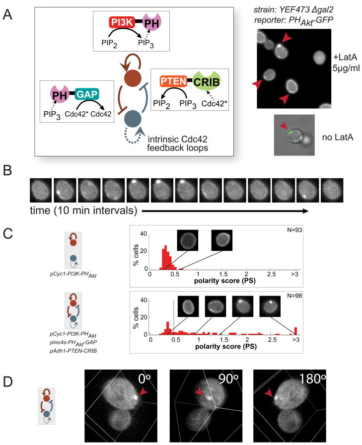
Figure 5. Experimental design of synthetic PIP3 polarization networks.
(A) Three regulatory links were introduced into a yeast strain by expressing all three synthetic fusion proteins from our toolkit. Several cells in one field of view show PIP3 polarization with this most robust combination of polarization motifs (top right). In most cases, cells were treated with 5μg/ml Latrunculin A (LatA) before imaging to prevent budding. When omitting LatA treatment, PIP3 (green) polarizes away from the bud site (phase), where Cdc42* is concentrated. (B) Timecourse of PIP3 polarization demonstrates that they are dynamic but can persist for over tens of minutes (10 minute intervals between images). (C) Histograms of polarity scores (PS). Positive feedback alone (top) produces a small number of weak poles. The three-motif (bottom) combination produces significantly larger numbers of strong poles. Example images of a range of polarity scores are shown. N indicates the number of individual cells analyzed with each network topology. Maximum polarity score for each cell through observation is shown. See also Figures S5 and S6. (D) A three-dimensional rendering of a cell with polarized PIP3 (See also Movies S1 and S2).

