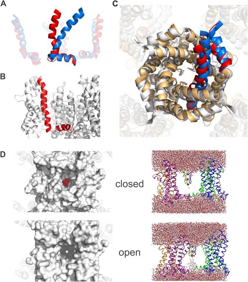
FIGURE 3.
Closed state model satisfying LRET restraints. A, from the open (blue) to the closed (red) state, the S4 helix undergoes a translocation of 9 Å along its axis together with a rotation of 37° relative to the S4-S5 linker and of 24° around its own axis. B, in its resting state, the lower S4 maintains a 310-helical conformation. The S4-S5 linker is slightly bent. C, the 4 Å radial displacement of the S4-S5 linker is transferred to the C-terminal part of the S6, therefore closing the internal gate. White, the open state crystal structure (2R9R); light orange, the closed state model. One subunit is highlighted in blue (open) and red (closed). It shows the small displacement that is sufficient for pore closing. D, the water-filled column is interrupted in the bottom part of the pore when the internal gate is closed in our model (top) in comparison with the open state (bottom). For clarity, only the voltage sensors, linkers, and selectivity filter are shown. On the left, the view into the pore of closed model and open structure are shown. The pore is sealed by the ring of isoleucines Ile-398 (highlighted in red) in the closed model, whereas the selectivity filter is freely accessible in the open crystal structure (2R9R).

