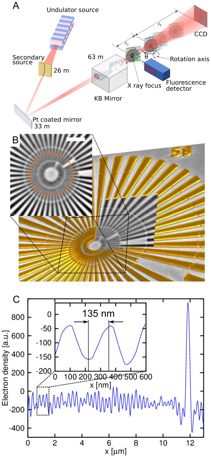
Figure 1. Principle of correlative nanolaminography.
(A) Schematic of the nanolaminography setup on ID22NI at the ESRF. The beam is focused by multilayer coated Kirkpatrick-Baez optics. The specimen is placed in the focus to raster scan the fluorescence spectra. The specimen is placed downstream of the focus to obtain a full-field magnified holographic image on the 2D detector. The tomographic rotation axis is inclined by the laminographic angle θ with respect to the beam direction. (B) 3D rendering of a lithographically fabricated Siemens star test pattern: the window reveals a single slice from the reconstructed 3D volume and the inset shows the center of the test pattern (scale bar 2 µm). (C) Profile plot along the circle shown in panel b. The inset shows a 135 nm half period achieved as lateral resolution in the 3D image.

