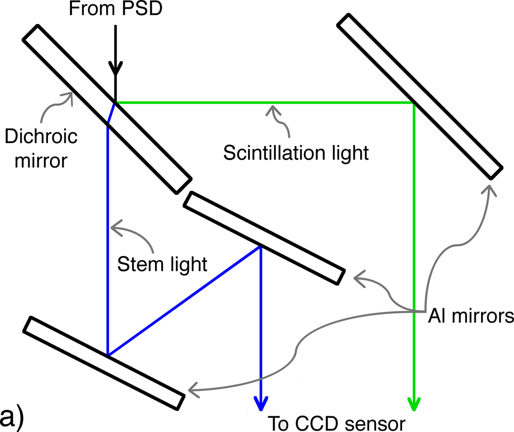
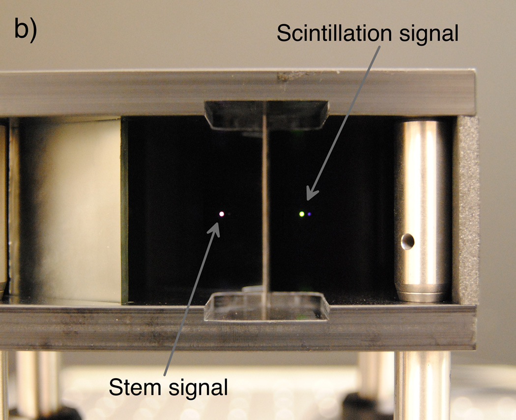
Figure 1.
(Left) Diagram depicting an overhead view of the optical system, in which the incoming light from the PSD is split into beams of scintillation (reflected ray) and stem (refracted and transmitted ray) light by the dichroic mirror. The optimized design allows for minimal yet equal path lengths between the PSD output and the objective lens attached to the camera. (Right) A photograph of simulated PSD output (room light through a fiber-optic cable) taken through the mirror setup prior to installation of the camera and light tightening.


