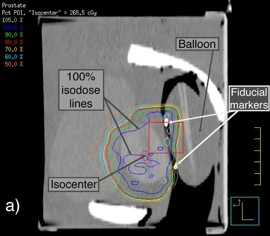
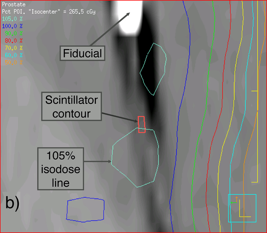
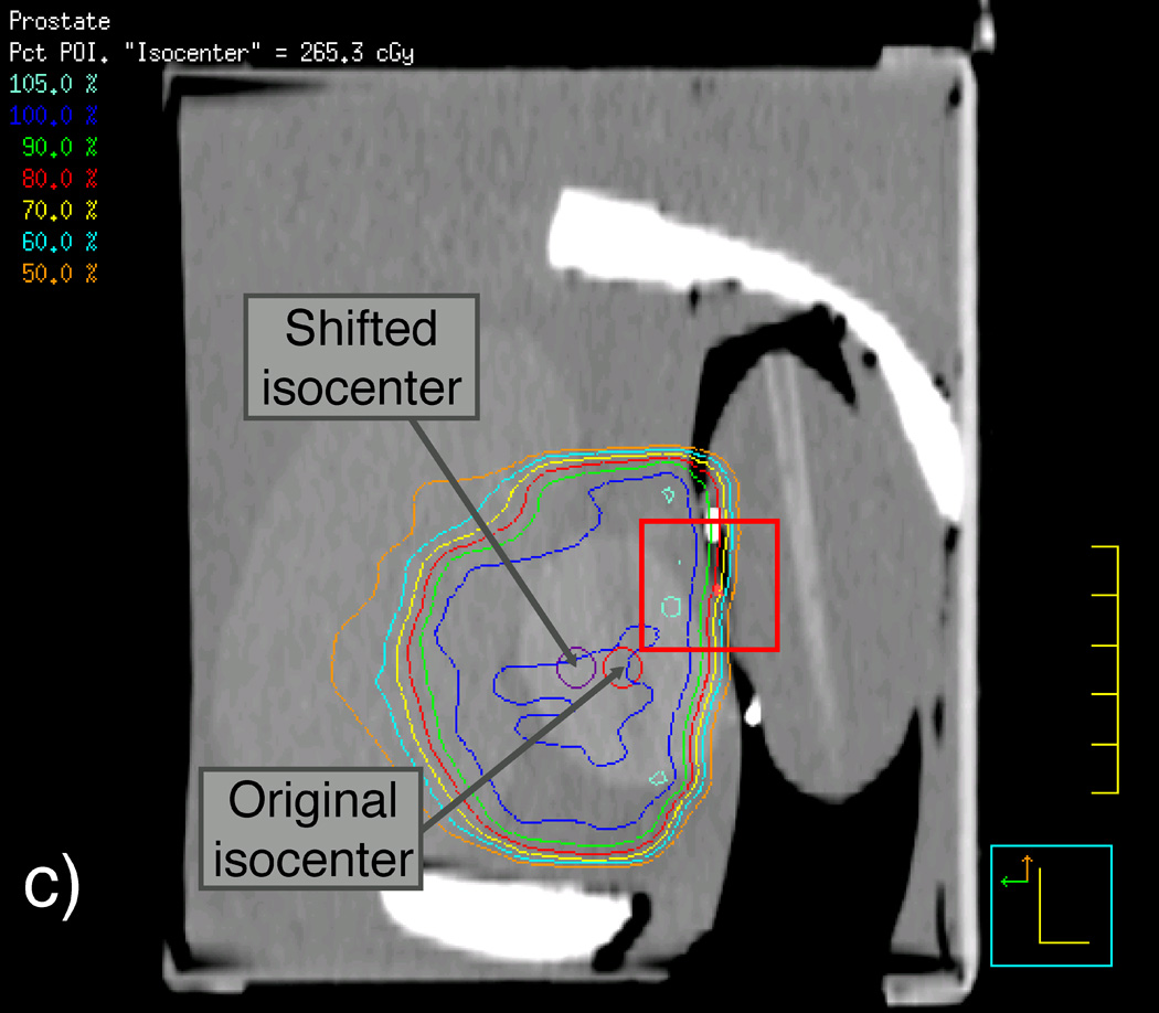
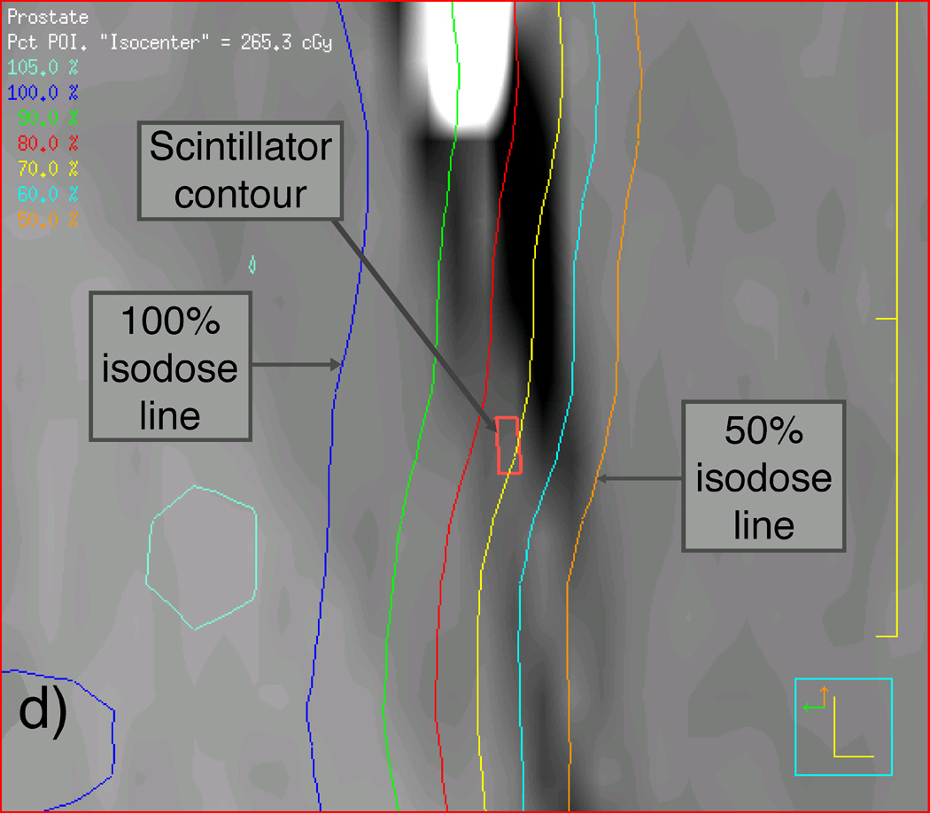
Figure 3.
Labeled sagittal CT reconstructions of the deformable phantom with the water-filled detector balloon inserted. (a) View of the whole phantom showing isodose lines of the IMRT plan with the isocenter approximately centered in the synthetic prostate. (b) Zoomed-in view of CT reconstruction (including detector contour and isodose lines) contained within the rectangle shown near the center of (a). (c) View similar to that shown in (a), but with the IMRT plan focused on an isocenter shifted 1 cm anterior to the original isocenter. (d) Zoomed-in view of contents of the rectangle shown in (c), showing the detector contour lying within the dose gradient of the IMRT plan.


