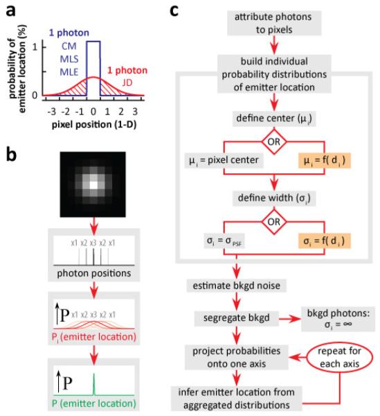
Fig. 1.
JD localization. (a) An individual photon carries information about the probability of an emitter’s location. CM/MLS/MLE (blue) assume equal probability throughout the pixel, with zero probability elsewhere; JD localization (red) uses a normal distribution to emulate microscope PSF (FWHM = 2.8x pixel width) which spreads beyond the pixel (shaded area The area under both curves is equal. (b) Principles behind JD localization. Each photon represented in a pixel is treated individually (1, 2, and 3, photons indicated by x1, x2, x3), individual probabilities of the location of the emitter, Pi (red curves) are aggregated to yield the joint probability, P, of emitter location (green). (c) Flow diagram for JD localization. Photons are attributed to each pixel dependent on intensity, and a probability distribution of the source of each photon is built using peak location (μi) and width (σi). The peak can be located at pixel centre (left) or anywhere within or outside the pixel (right); the width can be that of PSF (left) or any arbitrary value (e.g., as a function of distance, di, from the most intense pixel; right). Background (bkgd) noise is estimated and the influence of background photons nullified by setting σi = ∞. Then, probabilities of individual photons are projected onto a single axis, combined to infer the probability of emitter location for that axis, and the projection and inference repeated for each axis.

