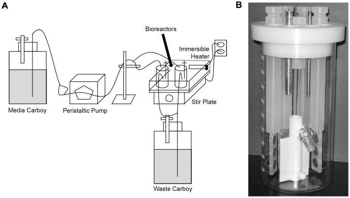
Figure 1. Schematic of the bioreactor system.
(A) Representation of system set-up. Medium was pumped from the media carboy to the reactors by using a peristaltic pump. The bioreactors themselves were in a water bath that was maintained at 30°C by the use of an immersible aquarium heater. The bioreactors were kept spinning at a constant rpm over the course of the experiment. Liquid exited the bioreactors by gravity into a waste carboy. (B) Close-up view of the CDC biofilm reactor. The bioreactor has openings for 8 polypropylene rods. Each rod (four shown here, for clarity) contains three spaces for stainless steel coupons which can be removed to assay for bacterial CFU. At the center of the bioreactor is a stirring baffle that maintains constant shear stress. There is a spout located about 1/3 the length of the vessel from the bottom to allow for the exit of media.

