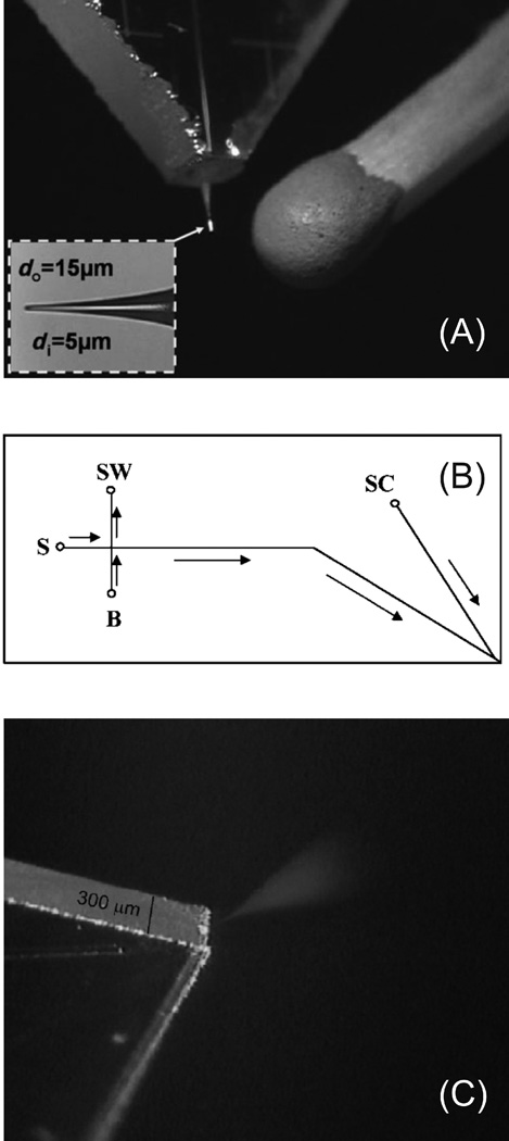
Figure 6.
(A) Image of an integrated ESI tip at the edge of a glass CE microchip that was fabricated by pulling a CNC-milled cone using a Pt heating coil. (B) Schematic of a corner ESI microchip for CE-MS. Arrows indicate the direction of flow. Separations are performed by applying a separation voltage to the buffer reservoir (B) and an ESI voltage to the side channel (SC). (C) Image of a corner ESI microchip electrospray. (Modified from refs. (A) [148] and (B) and (C) [150] with permission. ©2007 Wiley-VCH and © 2008 American Chemical Society, respectively.)

