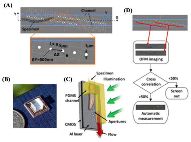
Figure 10.
(A) A schematic diagram of OFM. The apertures (white circles) are fabricated directly on top of the optoelectronic sensor and incorporated in an optofluidic channel (blue lines). (B) A photograph of the OFM. (C) A schematic diagram that shows that by tilting the microscope, gravity can provide the flow of the sample. (D) Block diagram of OFM computational principles. Reprinted from reference 92 with permission from National Academy of Sciences, USA.

