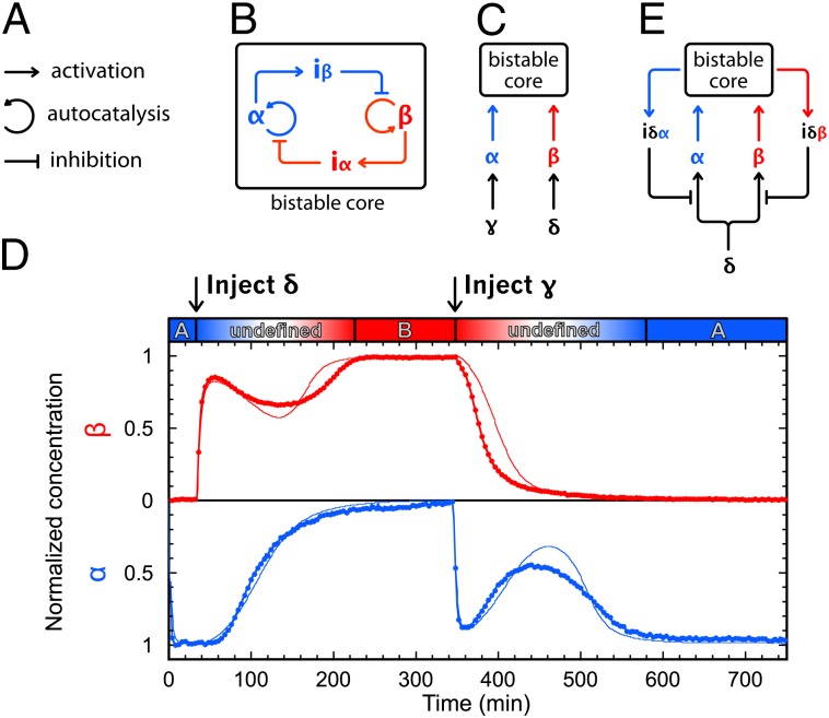
Fig. P1.
Modular assembly of in vitro memory circuits. (A) The three modules of the DNA toolbox. (B) Bistable circuit: α activates the production of inhibitor iβ, which inhibits the production of β. Similarly, β activates the production of inhibitor iα, which inhibits the production of α. (C) Switchable memory circuit: two activation modules are wired to the bistable core. They take two different external inputs, γ and δ. (D) Experimental (thick line) and fitted model (thin line) time plot of the normalized concentration (1 for the steady state and 0 for the lowest) of α and β. The switchable memory circuit starts on state A, switches to B on injection of δ, and then switches back to A on injection of γ. (E) Push-push memory circuit: two additional inhibition modules feed the state of the bistable element back to the input, providing state-dependent switching upon injection of the same exogenous input.

