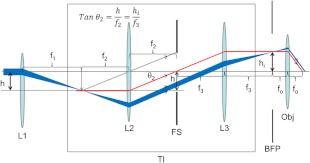
Fig. 3.
Ray diagram for the Olympus TIRF illuminator (TI) and adjacent optical elements in the excitation beam. Illumination by the factory installed fiber optic bypasses lens L1 placing the point source of the fiber tip at the focal plane of L2 with light pathway indicated by the red line. The airborne laser is coupled to the TI via L1 with focal length . L1 is displaced distance from the optical axis of the TIRF illuminator. The beam follows the pathway indicated in the blue ray diagram. L1 displacement, , produces a focused beam at the BFP with height and magnification given by the ratio of focal lengths, . The objective is shown with focal length . Field stop, FS, controls the lateral size of the illuminated region at the focal plane of the objective.

