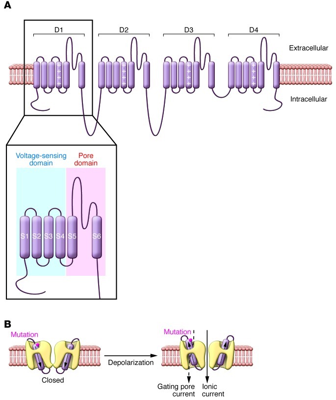
Figure 1. Voltage-gated sodium and calcium channel structural domains and location of gating pore.
(A) Predicted transmembrane topology model of typical voltage-gated sodium or calcium channel. The S4 segments within voltage-sensing domains are indicated by a column of plus (+) signs. The inset illustrates locations of the separate voltage-sensing and pore domains that are repeated four times in the channel protein. (B) A cutaway view showing the pathway through which ionic current or gating pore currents are conducted. The cylinders within the channels represent the S4 segments, and the approximate location of the HypoPP mutation CaV1.1 R528H is indicated. Figure modified from the Journal of General Physiology (23).

