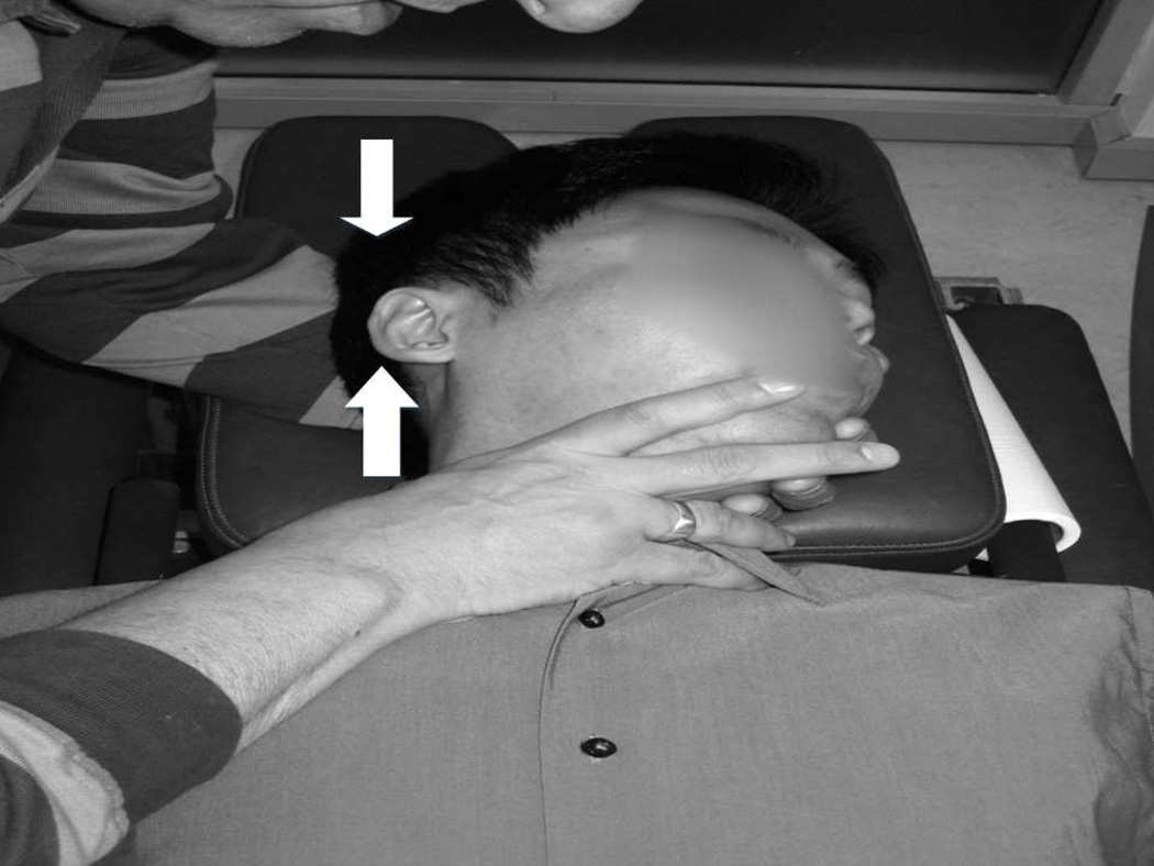
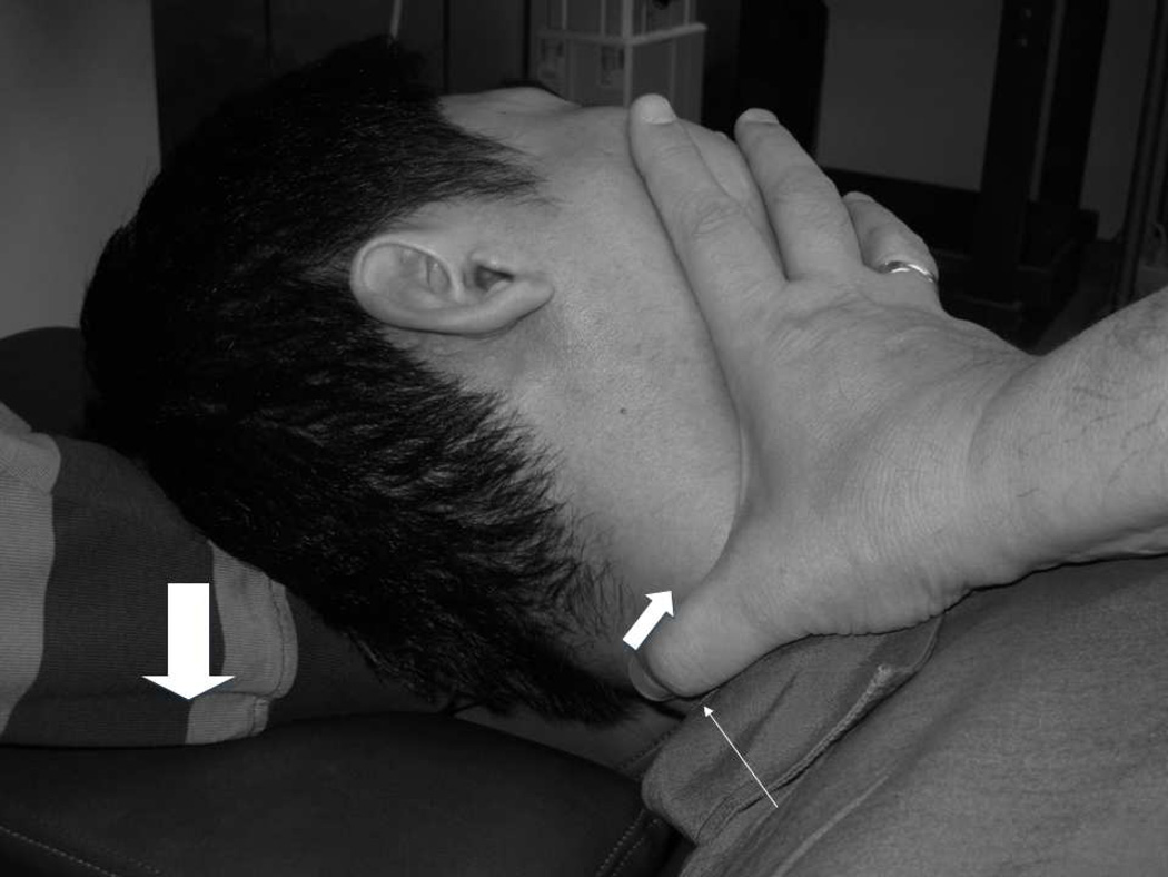
Figure 2.
RM configuration; the wide arrow shows the force to trip the cam and the thinner arrow gives one component of the intended treatment force.
RM configuration; the wide arrow as in 2a; the manual contact with the operator’s thumb (thin arrow) and direction of second intended component (thinnest arrow) are shown (head is over-rotated to show thumb contact).


