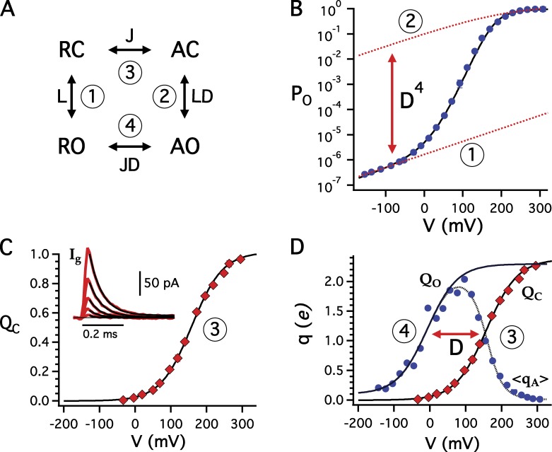
Figure 3.
The energetics of voltage sensor/gate coupling. (A) Voltage sensor/gate states in a single subunit. Numbers refer to data in B, C, and D used to determine the indicated equilibrium constants. (B) PO-V determines L (1) and LD4 (2). Dashed lines indicate the predicted voltage dependence of PO with all voltage sensors either in the resting or activated state and zL = 0.3 e. (C) Normalized QC-V for closed channels determined from ON gating currents (inset) is fit by a Boltzmann function with zJ = 0.58 e and defines J (3). (D) QO-V relation for open channels defines JD (4). QO is estimated by fitting the foot of the qa-V relation (qa = kTdln(PO)/dV) with a Boltzmann function. The shift between QO and QC relations defines the coupling factor D.

