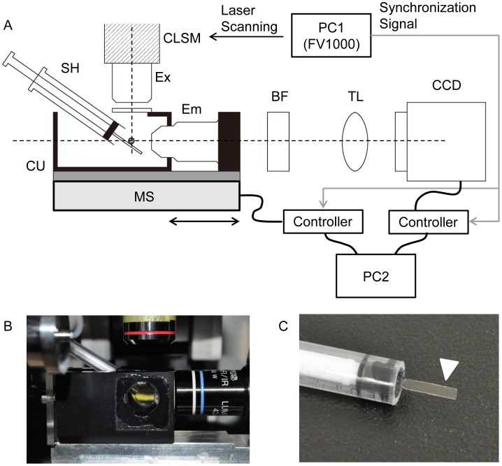
Figure 2. Setup of ezDSLM for observation of amoeboid movements.
(A) Side view of the instrument (not to scale). Optical axes of objectives for excitation (Ex) and emission (Em) are shown in dashed lines. The illumination optics were derived from the confocal laser scanning microscope (CLSM). Specimens were placed on the sample holder (SH) in the chamber unit (CU) filled with medium. The CU containing the objective for emission detection is mounted on a movable motor stage. BF, barrier filter; TL, tube lens; CCD, CCD camera. (B) Photograph of the chamber unit. (C) Photograph of the sample holder. Amoebae were placed on the cover glass for imaging (arrow head).

