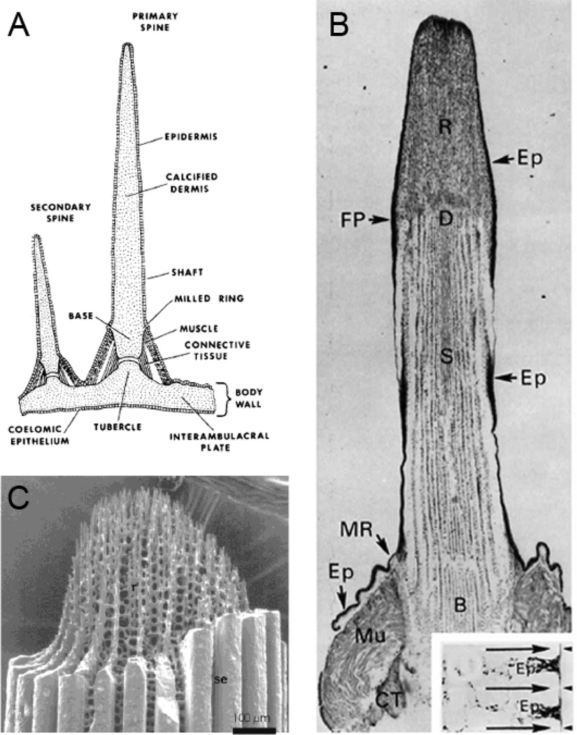
Figure 2.
A. Schematic of the attachment of primary and secondary spines to a test plate [15]. B. A longitudinal section of a decalcified primary spine, revealing the organic matrix of the dermis D, within the base B, shaft S, and regenerate (repaired fracture, at fracture plane, FP) tissue, R. At the base, are the structures called the milled ring, MR, and the Muscle attachment, Mu. The clear spaces within the shaft and regenerate mark the locations of the mineral phase calcite. Ep denotes the epidermis. As shown in the transverse section in the inset, the Ep invaginates between calcite septa at the shaft surface [15]. C. A spine regenerate tip clearly showing the fenestrated calcite, as well as the heavy calcite septa (Se) surrounding the shaft, also shown in the FP cross section in the inset in 2b [16]. Reproduced with permission.

