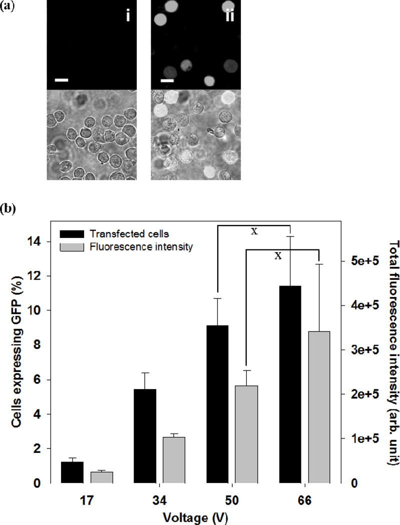
Figure 6.
Effect of voltage on DNA transfection by electroporation with a microneedle electrode device. (a) Representative confocal microscopic images of the human prostate cancer cells at 24 h after intracellular delivery of pDNA expressing GFP using a 2 ms square wave pulse. The top row presents images from the green fluorescence channel showing cells with GFP expression, and the bottom row shows the combination of bright field and fluorescent images. Additional images can be seen in Supplemental Figure S4. (i) Unpulsed control, (ii) 67 V. (scale bar = 20 µm). (b) GFP transfection efficiency at different voltages. Black bars represent the percentage of cells expressing GFP and gray bars represent total green fluorescence intensity in cell populations. Data represent the average of n=3 replicate experiments. Standard deviation bars are shown. × not significantly different (Student’s t-test, p > 0.05)

