
Figure 1. Schematic description of the epiTED Imaging System.
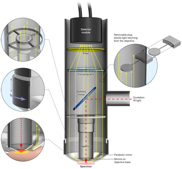
The epiTED system is built around an LSM Technologies objective inverter system. In this scheme the objective inverter is attached to the turret of an inverted microscope (not shown). The pulsed infrared light travels through the inverter to the dicroic mirror positioned in the main tube and through the objective for excitation. Emitted fluorescent light is directed to the detector module through both the objective and the parabola. Aluminum foil tape adhered to the face of the objective allows for somewhat more efficient light collection by the parabola (shown here idealized as small mirrors –see discussion). The left top inset shows the ring holding the objective. The middle left inset shows the focusing mechanism for the parabola. The left bottom inset shows potential paths for the redirected light collected by the parabola. The right inset illustrates the objective blocking element used for testing the amount of emitted light collected solely by the parabola. Details of the elements used in the construction of this device can be found in the Materials and Methods section.