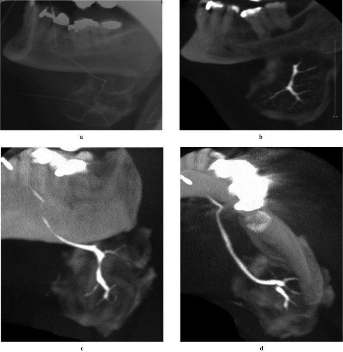
Figure 3.
Sialogram of the left submandibular gland using the proposed preliminary protocol detailed earlier. (a) Lateral skull plain radiograph of the gland following contrast administration. This image was made prior to the cone beam CT (CBCT) scan to ensure adequate fill of the gland with contrast material, and it demonstrates the lack of visibility of the secondary and tertiary ductal structures due to extravasation of the contrast material into the gland capsule. (b) Reformatted sagittal CBCT image of the same gland with the secondary and tertiary ducts clearly visible. Maximum intensity projection (MIP) CBCT images (c) in the coronal plane and (d) in the axial plane demonstrating the three-dimensional and multiplanar capabilities of CBCT. The CBCT images were acquired with the 15 cm FOV centred on the left submandibular gland and using X-ray tube factors of 80 kVp and 10 mA

