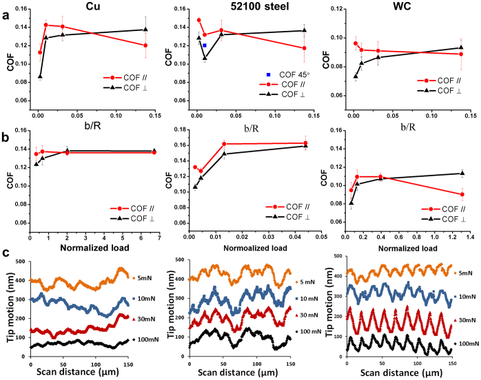
Figure 3. Friction characteristics from size-dependent and load-dependent tests.
(a) Friction anisotropy under the constant load of 5 mN with respect to the relative pattern size, b/R, corresponding to the groove bank sizes of 2, 8, 25 and 110 μm. (b) Friction anisotropy of the same grooves (8 μm) with respect to normalized load, defined as applied load over the critical load of yielding or failure, corresponding to the applied loads of 5, 10, 30 and 100 mN. (c) Real-time tip trajectories from the load-dependent tests. Note that the curves are separated with certain distance for clarity. The mating tips are 304 stainless steel balls (R = 800±3 μm, RMS roughness = 151±2 nm), and the scan speed was 1 μm/s for all of the above experiments.

