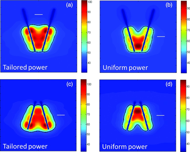
Figure 8.
Temperature maps and extents of the ablation zone after 10 min ablations with two applicators inserted in converging (a and b) and diverging (c and d) implants. When power supplied to individual transducers is tailored along the length of the applicators (a and c), there are no clefts or indentations in the ablation zone. However, applying uniform powers to all transducers results in hotspots where applicators are closest to each other, and clefts or indentations in the ablation zone where applicators are furthest apart. The white line in each panel corresponds to a 1 cm scale.

