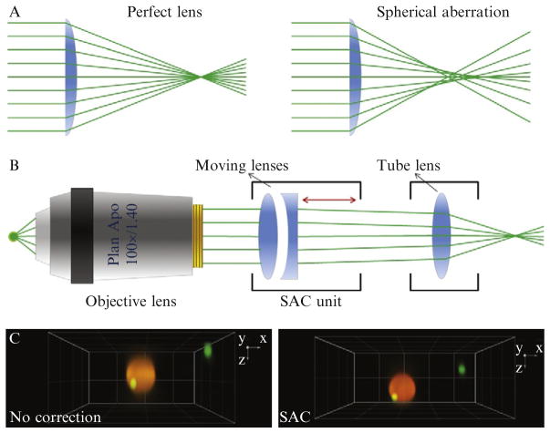
Figure 4.4.
Spherical aberration. (A) Schematic representation of ray paths in the absence and presence of spherical aberration. (B) Representation of the optical hardware used to correct spherical aberration. (C) Fluorescence image of two beads of different size acquired in three dimensions using the spinning-disk confocal microscope, in the absence (no correction) and presence (SAC) of spherical aberration correction. Note the increase in fluorescence intensity and decrease in the axial elongation of the diffraction-limited bead.

