
Fig. 1.
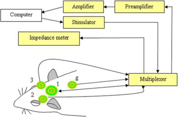
Schematic representation of the experimental setup. The TFS was applied between the outer ring and the middle disc of electrode (1). Electrodes (1), (2), and (3) were used for recording. Electrode (g) was the ground. A personal computer was used to control the system and store the data.