Abstract
In many mammalian species, the removal of one lung (pneumonectomy) is associated with the compensatory growth of the remaining lung. To investigate the hypothesis that parenchymal deformation may trigger lung regeneration, we used microCT scanning to create 3-dimensional finite element geometric models of the murine lung pre- and post-pneumonectomy (24 hours). The structural correspondence between models was established using anatomic landmarks and an iterative computational algorithm. When compared with the pre-pneumonectomy lung, the post-pneumonectomy models demonstrated significant translation and rotation of the cardiac lobe into the post-pneumonectomy pleural space. 2-dimensional maps of lung deformation demonstrated significant heterogeneity ; the areas of greatest deformation were present in the subpleural regions of the lobe. Consistent with previously identified growth patterns, subpleural regions of enhanced deformation are compatible with a mechanical signal—likely involving parenchymal stretch—triggering lung growth.
Keywords: finite element, lung, image registration, regeneration, pneumonectomy
1. Introduction
The shape of the lung, reflecting the elastic properties of alveolar septae and transpleural pressures, is relevant to both normal respiratory function and lung regeneration. During normal tidal breathing, the lung demonstrates relative shape stability and geometric similarity (Miki et al., 1993); that is, the shape of the lung remains relatively constant despite a change in lung volume. Computational modeling during normal breathing has largely focused on the mapping of lung motion relevant to the targeting of radiation therapy for lung tumors (Al-Mayah et al., 2008, Werner et al., 2009).
In contrast, there is a fundamental change in the shape of the lung—independent of tidal ventilation—after the surgical removal of lung tissue. In rodents, microCT imaging after the removal of the left lung (pneumonectomy) has suggested a significant change in the shape of the remaining right lung (Gibney et al., 2012). Subsequent analyses of the remaining lung, and the cardiac lobe in particular, have demonstrated significant increases in volume, weight, and cell number (Chamoto et al., 2012, Konerding et al., 2012, Lin et al., 2011). The shape instability of the post-pneumonectomy lung suggests a mechanical or stretch signal for compensatory growth; however, the deformational changes in the remaining lung after pneumonectomy are poorly understood.
In this report, we used pre- and post-pneumonectomy microCT scanning to create finite element models of the murine cardiac lobe. We characterized the deformation of the post-pneumonectomy lung with an iterative nonrigid spatial transformation. Our finite element models were used to map lobar deformation and predict regions of regenerative growth within the murine cardiac lobe.
2. Pneumonectomy and imaging
Mice
C57/B6 mice (Jackson Laboratory, Bar Harbor, Maine), 22 to 30gm, were used in all experiments. The care of the animals was consistent with guidelines of the American Association for Accreditation of Laboratory Animal Care (Bethesda, MD).
Orotracheal intubation and ventilation
Orotracheal intubation was performed with the animal suspended by the incisors and the tongue gently retracted anteriorly. A 20G angiocatheter (BD Insyte, Sandy, Utah) was passed between the vocal cords under direct illumination. Anesthesia for orotracheal intubation was a mixture of 100mg/kg Ketamine (Fort Dodge Animal Health) and 0.6mg/kg Xylazine (Phoenix Scientific, Inc., St. Joseph, MO) administered intraperitoneally. For subsequent CT imaging, the mouse was maintained on 0.5% isofluorane, a respiratory rate of 200 bpm and a tidal volume of 10 ml/kg.
Pneumonectomy
Mice were intubated with a 20g angiocatheter (BD Insyte, Sandy, UT) and ventilated with a Flexivent rodent ventilater (SCIREQ, Montreal, QC Canada) using standard settings of 200 bpm, 10 ml/kg, a pressure limit of 30 cmH2O and a PEEP of 3 cmH2O (Gibney et al., 2011). A left thoracotomy was performed through the 5th intercostal space, the hilum ligated with a 6-0 silk tie (Ethicon, Somerville, NJ), and the lung sharply excised distal to the ligature. A recruitment maneuver was performed to recruit the contralateral lung and medialize the mediastinum as the thoracotomy was closed. The mouse was extubated and transferred to a warmed cage until recovered from the anesthesia.
CT scans
CT scans alone were obtained with a GE eXplore 120 CT scanner at 50um/pixel resolution. The serial DICOM images were exported for use in custom finite element software previously described (Kojic et al., 2008, Milasinovic et al., 2008).
3. Numerical Method
Geometric model
We used a detailed image algorithm based on the 3D image reconstruction of the cardiac lobe both pre- and post-pneumonectomy. The 3D image model was created by combining the sequential 2D segmented images into one matrix image file. Using the matrix file, the boundary surface of the 3D mesh was constructed based on the marching cubes algorithm (Milasinovic et al., 2008). The surface was idealized using a standard Laplacian smoothing algorithm and surface cleaning. Using a connectivity analysis previously described (Tsuda et al., 2008), the cardiac lobe was isolated from the rest of the lung. The resulting geometric models, typically about 81,000 3D 8-node finite elements using unstructured discretization, provided a faithful reproduction of the cardiac lobe observed in vivo. The central axis of the cardiac lobe airway, branching from the right mainstem bronchus, was used as a reference point for translation and a reference axis for rotation calculations.
Spatial correspondence of pre- and post-pnemonectomy lung
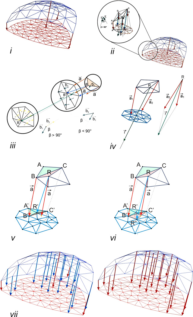
The registration of pre- and post-pneumonectomy lung images was approached using a nonrigid spatial transformation. The number of surface finite elements in the post-pneumonectomy geometric model (Figure 2i, red mesh) was larger than in the pre-pneumonectomy model (Figure 2i, blue mesh). The spatial correspondence was established with the following iterative steps:
Step 1: Define the "key" connections between the corresponding nodes in the pre- and post-pneumonectomy geometric models. Manually selected based on anatomic landmarks, the key nodes (Figure 2i, red arrows) provided structural correspondence that was interpolated by the subsequent automated steps of the algorithm. The number of key nodes, particularly relevant for concave surfaces, directly contributed to mapping accuracy and the increased number of elements in the post-pneumonectomy analysis.
- Step 2: Define nodes neighboring the landmark or “key” nodes. For the nodes neighboring the key node (Figure 2ii, B, C, D), the algorithm automatically identified the corresponding node (B’, C’, D’) in the post-pneumonectomy mesh by the following search process:
- Assign a vector a⃗ (= AA’ ) to each non-key node of the pre-pneumonectomy mesh. The vector a⃗ functions as a direction vector (Figure. 2 ii inset).
- Evaluate connections between the node under consideration (e.g. node B) and the neighboring nodes in the post-pneumonectomy mesh (e.g. the node B’, C’, or D’).
- Identify the vector (among BB’, BC’, or BD’) defining the smallest angle with a⃗; this vector provides a tentative identification of the corresponding node (e.g. node B’) in the post-pneumonectomy mesh. BB’ and is referred to as a temporary connection (Figure 2ii, blue arrows).
-
Exclude elements on the surface of the mesh by restricting the angle between b⃗1 and b⃗2 to less than 90 degrees (Figure 2iii, middle); an angle greater than 90 degrees identifies a surface with an opposite orientation (Figure 2iii, left).For the case of a node (e.g. R) with two or more key nodes in their neighborhood (Figure 2iv),
- Calculate the sum of the vectors of the nearest “key” connections, a⃗1(= A1A1’) and a⃗2(= A2A2’), and assign the resulting r⃗ (= a⃗1 + a⃗2) to the node R as a direction vector (Figure 2iv).
- Repeat (c) using r⃗ instead of a⃗, to identify a temporary connection.
- Repeat (d) to ensure the proper orientation of surface element.
Step 3: Check the validity of the newly formed temporary connections. Test whether the newly identified corresponding node R’ is located within an existing element created in the previous iterations (Figure 2v). After satisfying the required conditions, the connection RR’ is considered “permanent”. It will be used as a “key” connection in the next iteration (Figure 2vi).
Step 4: The iteration is repeated until all connections are assigned to all nodes in the pre-pneumonectomy mesh (Figure 2vii).
Figure 2.
The registration of pre- and post-pneumonectomy lung images was performed using a nonrigid iterative algorithm. Landmarks and surface features were used to identify initial "key" connections between the corresponding nodes in the pre- and post-pneumonectomy geometric models (i). The manually selected key nodes (Figure 2i, red arrows) provided structural correspondence that was interpolated by the subsequent automated steps of the algorithm (ii-vi). With successive iterations, the number of key nodes increased until all nodes in the pre-pneumonectomy mesh were assigned.
Deformation
The microCT imaging experiments demonstrated a substantial change in the shape of the cardiac lobe in the pre- pneumonectomy (undeformed configuration) and in the post- pneumonectomy (deformed configuration). Because the deformation of the remaning lung was not infinitesimal, we applied large deformation theory (Malvern, 1969); that is, the differential vector, dx in the post-pneumonectomy object was mapped from the original differential vector dX in the pre- pneumonectomy using the deformation gradient tensor D͂
| (1) |
where , , and
Since the deformation gradient tensor D͂ can be decomposed into a product of the rotation tensor R͂ and the stretch tensor S͂ using the polar decomposition theorem (Eringen, 1962), the total deformation (i.e., a product of rotation and stretch) can be expressed by D͂. Total deformation was expressed as the “relative deformatin index” (RDI); a dimensionless measure reflecting the product of stretch and rotation.
Finite element procedure
In general, the finite element equation of balance of linear momentum can be derived from the fundamental differential equations of balance of forces acting at an elementary material volume. By applying the principle of virtual work, the differential equations of motion of a finite element are obtained as
| (2) |
where M͂ is the mass matrix; B͂W is the damping matrix; K͂ is the stiffness matrix; and U and Fext are the nodal displacement and the external nodal force vector which includes body and surface forces acting on the element, respectively. In the present analysis, we excluded intertial and viscous terms. Differential equations further integrated according to equation are:
| (3) |
where the tissue stiffness matrix K͂tissue and vector n+1F were expressed in terms of the matrices and vector described previously (Hoffmann & Rossignac, 1996). Notably, this equation reflected the assumptions of a linear elastic material and small displacement.
In the case of post-pneumonectomy shape change, the large wall displacements created a geometrically nonlinear, but materially linear problem. Because of the uncertain assumptions of equation (3), we used the previously described incremental-iterative equation (Kojic et al., 2008):
| (4) |
where ΔU(i) were the nodal displacement increments for the iteration ‘i’, and the system matrix , the force vector n+1F(i−1) and the vector of internal forces n+1Fint(i−1) correspond to the previous iteration. The geometrically linear part of the stiffness matrix, , and nodal force vector, n+1Fint(i−1), were defined in equation:
| (5) |
where the consistent tangent constitutive matrix of tissue and the stresses at the end of time step n+1σ͂(i−1) depended on the material model used. Calculation of the matrix and the stresses n+1σ͂(i−1) for the tissue material models used in these applications.
4. Results
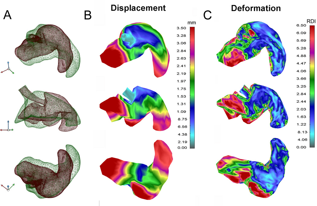
The 3D geometric models were constructed with a greater number of surface elements in the post-pneumonectomy object (35,210 elements) than in the pre-pneumonectomy object (6348 elements) to ensure accurate feature correspondence in the post-pneumonectomy model. The average finite element model was composed of 81,100 3D 8-node elements. The models demonstrated important differences between the pre- and post-pneumonectomy lung (Figure 3). Most notably, there was significant displacement of the cardiac lobe into the left hemithorax (Figure 3B, ellipse). There was significant translation and rotation of the cardiac lobe into the post-pneumonectomy pleural space as well as displacement of the tip as the apparent result of contact with the chest wall. In addition, superimposition of the pre- and post-pneumonectomy mesh demonstrated a significant change in the shape of the cardiac lobe (Figure 3C). More than the other 3 lobes of the right lung, the cardiac lobe demonstrated the greatest displacement and shape change; perhaps not coincidently, the cardiac lobe also demonstrates the greatest increase in post-pneumonectomy lung growth (Gibney et al., 2012).
Figure 3.
Geometric models of both lungs before (A) and the remaining right lung 24 hours after (B) pneumonectomy. C) Geometric models of the cardiac lobe (B, elipse) before (green) and after (red) pneumonectomy were superimposed and presented in 3 projections (superior, anterior, inferior). The cardiac lobe airway was used as a reference point for translation and reference axis for rotation.
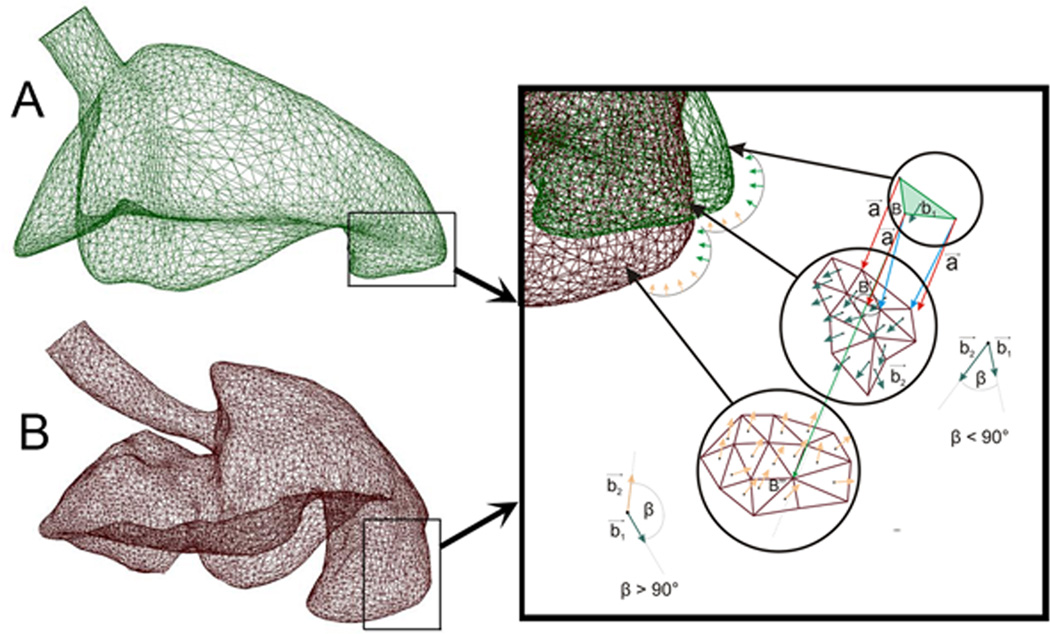
To identify structural correspondence between the pre- and post-pneumonectomy cardiac lobes, 40 landmarks reflecting identifiable surface features were identified in both models (Figure 4). Referred to as “key” features, the key nodes provided an anchor for subsequent algorithmic mapping of the pre- and post-pneumonectomy surface elements. In comparing the models, an interesting finding was the discordance between the displacement and deformation of the cardiac lobe (Figure 5). Areas of the lung with the greatest displacement, such as the lateral tip of the cardiac lobe (illustrated in Figure 4), did not demonstrate significant deformation. In contrast, the posterior aspect of the cardiac lobe had minimal displacement, but significant deformation.
Figure 4.
Structural correspondance of surface features of the pre-pneumonectomy (A) and post-pneumonectomy (B) finite element model. Inset shows the implementation of step 2d (see 3. Numerical Method); the procedure to ensure the proper orientation of the surface elements.
Figure 5.
Displacement and deformation of the cardiac lobe after calculating relative displacement of pre-pneumonectomy and post-pneumonectomy models of the cardiac lobe. A) The superimposed pre- (green) and post-pneumonectomy (red) models were used to calculate displacement (B) and parenchymal deformation (C).
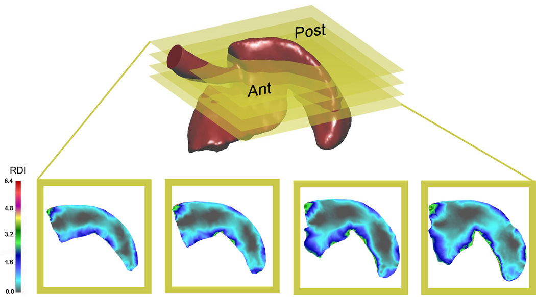
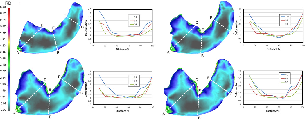
To provide a 2D map of parenchymal deformation, analogous to tissue sections obtained in standard histology, the finite element model of the cardiac lobe was serially sectioned in the transverse plane (Figure 6). The 2D maps of the cardiac lobe demonstrated that areas of greatest deformation were consistently present in the subpleural regions of the lobe. Subpleural regions of enhanced deformation and central regions of limited deformation, were consistent with the growth patterns previously identified by microCT and scanning electron microscopy (Konerding et al., 2012); that is, subpleural regions of the cardiac lobe demonstrating signficant sprouting and intussusceptive angiogenesis.
Figure 6.
Transverse sections of the cardiac lobe, analogous to histologic sections, were defined for four distinct planes in the lobe. Total deformation, reflecting the product of stretch and rotation, was mapped to the 2D sections. Ant=anterior or ventral surface; Post= posterior or dorsal surface.
To obtain a comparative measure of deformation, transept regions of interest (ROI) were drawn across the planar sections of the cardiac lobe (Figure 7). In general, the displacement of the subpleural regions exceeded, by more than 2-fold, the displacement of the central regions of the lung. Heterogeneity was also noted within these subpleural regions. In general, subpleural regions with significant positive (Figure 7, point ‘A’) and negative (Figure 7, point ‘E’) curvature appeared to have greater displacement than regions with less curvature. As noted previously, the posterior aspect of the cardiac lobe had the greatest deformation with approximately 2-fold increase over the corresponding region on the anterior surface of the cardiac lobe (Figure 7, D–E).
Figure 7.
Quantitative deformation of the cardiac lobe measured in four transverse planes. Transept regions of interest (ROI) drawn across the lobar section in three orientations (A–D, B–E, and C–F). The relative deformation, plotted as a function of distance, is shown in the adjacent graph. Deformation in the subpleural regions was consistently greater than in the center of the cardiac lobe. The posterior aspect of the cardiac lobe is defined by A-B-C; the anterior aspect by D-E-F.
5. Discussion
In this report, we used microCT imaging to develop finite element models of the pre- and post-pneumonectomy murine lung. In particular, geometric models of the cardiac lobe demonstrated significant displacement and deformation within the 24 hours after surgery. 2D "maps" of the cardiac lobe deformation were strikingly similar to regions of growth previously documented by histology and imaging studies (Konerding et al., 2012); that is, both deformation and growth occurred in sublpleural regions of the cardiac lobe. The spatial coincidence of parenchymal deformation and lung growth suggests a mechanical signal for triggering lung regeneration.
The principal finding of this report is that there was significant displacement and deformation in the cardiac lobe after pneumonectomy (Figures 3–7). Previous postoperative microCT scanning has indicated a 5 mm shift of the cardiac lobe into the left hemithorax (Gibney et al., 2012); here, we demonstrate that the cardiac lobe also demonstrated marked shape change within 24 hours of pneumonectomy. Since the shape changes occurred within 24 hours—prior to any change in the material composition of the lung (Lin et al., 2011)—the deformation appeared to be the result of transpleural pressure dynamics and not true lung growth.
Located in the inferior mediastinum, the cardiac lobe (also referred to as the infracardiac, postcaval, median and inferior lobe lobe) abuts the preoperative left lung and is contiguous with the post-pneumonectomy pleural space. We speculate that pneumonectomy leads to preferential stretch of the portion of the lung exposed to the pneumonectomy space. With continued diaphragmatic function bilaterally, the cardiac lobe experiences higher levels of cyclic stretch during breathing than more remote regions of the lung. We hypothesize that cyclic stretch, reminiscent of the role of stretch in lung development (Brody & Thurlbeck, 1986) and post-pneumonectomy humans (Butler et al., 2012), may be an important trigger for new lung growth.
The spatial scale of the cardiac lobe deformation reflected the scale of angiogenic growth previously observed in vivo (Konerding et al., 2012). Also consistent with in vivo findings (Konerding et al., 2012), our finite element model demonstrated significant variability in the degree of subpleural deformation. Similarly, our previous analysis of the post-pneumonectomy cardiac lobe has demonstrated discontinuous subpleural regions of angiogenic growth (Konerding et al., 2012). The integral scale of these regions of in vivo growth is strikingly similar to the areas of deformation described in our finite element model. We anticipate that a biologic test of our computational predictions could be obtained by spatial sampling techniques such as laser capture microdissection (LCM). We are currently using LCM to evaluate the angiogenesis-related transcriptional activity in the subpleural cardiac lobe.
A potential limitation of our study is that the lung deformation calculations were based on static lung images obtained at mid-thoracic volumes (20 cmH2O). Whereas this shape change reflected one aspect of deformation, a secondary consideration was the potential shape change associated with the dynamics of breathing. With each tidal breath, there is a change in lung volume. Whether this “cyclic” stretch participates in shape change, much less a “stretch” signal for lung growth is unclear. The development of respiratory-gated CT scanning should facilitate the analysis of potential shape change during the breathing cycle.
6. Conclusions
The change in the lung shape after pneumonectomy has been temporally associated with significant compensatory growth of the remaining lung (Hsia et al., 2004). In this report, we used microCT imaging and finite element modeling of the remaining lung after left pneumonectomy to demonstrate significant change in the shape of the cardiac lobe. Deformation of the cardiac lobe was heterogeneous, but concentrated in the subpleural regions of the lobe. We speculate that parenchymal deformation is an important trigger for regenerative lung growth.
Figure 1.
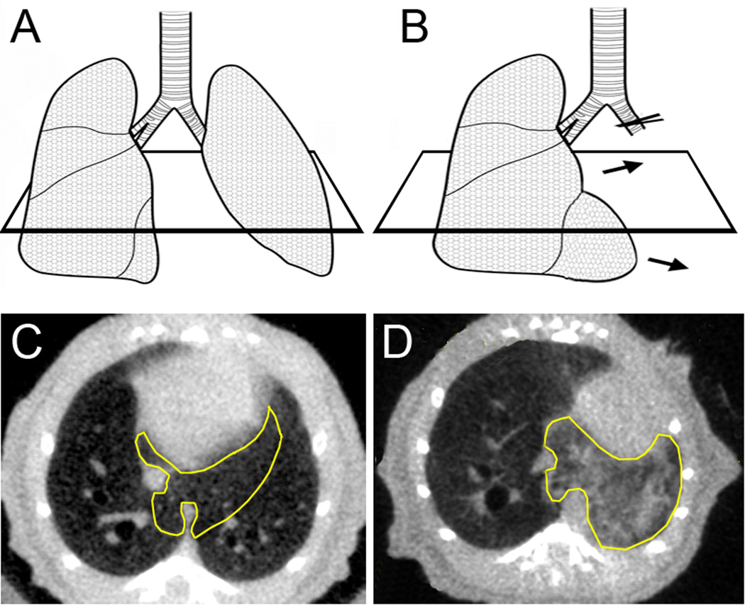
Schematic and transverse CT scan of the lung before (A,C) and 24 hours after (B,D) pneumonectomy. The cardiac lobe (yellow outline) demonstrates significant shape change within 24 hours.
Acknowledgments
Supported in part by NIH Grant HL94567, HL75426 and HL07734
Abbreviations
- 2D
2-dimensional
- 3D
3-dimensional
- LCM
laser capture microdissection
- ROI
Region of interest
- RDI
relative deformation index
Contributor Information
Nenad Filipovic, Email: nfilipov@hsph.harvard.edu.
Barry C. Gibney, Email: bgibney@partners.org.
Dalibor Nikolic, Email: markovac85@kg.ac.rs.
Moritz A. Konerding, Email: konerdin@uni-mainz.de.
Akira Tsuda, Email: atsuda@hsph.harvard.edu.
References
- Al-Mayah A, Moseley J, Brock KK. Contact surface and material nonlinearity modeling of human lungs. Phys. Med. Biol. 2008;53:305–317. doi: 10.1088/0031-9155/53/1/022. [DOI] [PubMed] [Google Scholar]
- Brody JS, Thurlbeck WM. Handbook of physiology. The respiratory system. Mechanics of breathing. vol. 3. Bethesda: Am. Physiol. Soc.; 1986. Development, growth, and aging of the lung; pp. 355–386. [Google Scholar]
- Butler J, Loring SH, Patz S, Tsuda A, Yablonskiy DA, Mentzer SJ. Evidence for lung growth in adult humans. N. Engl. J. Med. 2012;367:244–247. doi: 10.1056/NEJMoa1203983. [DOI] [PMC free article] [PubMed] [Google Scholar]
- Chamoto K, Gibney BC, Lee GS, Lin M, Simpson DC, Voswinckel R, Konerding MA, Tsuda A, Mentzer SJ. Cd34+ progenitor to endothelial cell transition in post-pneumonectomy angiogenesis. Am. J. Resp. Cell Mol. Biol. 2012 doi: 10.1165/rcmb.2011-0249OC. In press. [DOI] [PMC free article] [PubMed] [Google Scholar]
- Eringen AC. Nonlinear theory of continuous media. New York: McGraw-Hill; 1962. [Google Scholar]
- Gibney B, Houdek J, Lee GS, Ackermann M, Lin M, Simpson DC, Chamoto K, Konerding MA, Tsuda A, Mentzer SJ. Mechanostructural adaptations preceding post-pneumonectomy lung growth. Exp. Lung Res. 2012 doi: 10.3109/01902148.2012.715364. In press. [DOI] [PMC free article] [PubMed] [Google Scholar]
- Gibney B, Lee GS, Houdek J, Lin M, Chamoto K, Konerding MA, Tsuda A, Mentzer SJ. Dynamic determination of oxygenation and lung compliance in murine pneumonectomy. Exp. Lung Res. 2011;37:301–309. doi: 10.3109/01902148.2011.561399. [DOI] [PMC free article] [PubMed] [Google Scholar]
- Hoffmann CM, Rossignac JR. A road map to solid modeling. IEEE Trans. Vis. Comput. Graphics. 1996;2:3–10. [Google Scholar]
- Hsia CCW, Berberich MA, Driscoll B, Laubach VE, Lillehei CW, Massaro C, Perkett EA, Pierce RA, Rannels DE, Ryan RM, Tepper RS, Townsley MI, Veness-Meehan KA, Wang N, Warburton D. Mechanisms and limits of induced postnatal lung growth. Am. J. Respir. Crit. Care. Med. 2004;170:319–343. doi: 10.1164/rccm.200209-1062ST. [DOI] [PubMed] [Google Scholar]
- Kojic M, Filipovic NBSNK. Computer modeling in bioengineering: Theoretical background, examples and software. Chichester, England: John Wiley and Sons; 2008. [Google Scholar]
- Konerding MA, Gibney BC, Houdek J, Chamoto K, Ackermann M, Lee G, Lin M, Tsuda A, Mentzer SJ. Spatial dependence of alveolar angiogenesis in post-pneumonectomy lung growth. Angiogenesis. 2012;15:23–32. doi: 10.1007/s10456-011-9236-y. [DOI] [PMC free article] [PubMed] [Google Scholar]
- Lin M, Chamoto K, Gibney B, Lee GS, Collings-Simpson D, Houdek J, Konerding MA, Tsuda A, Mentzer SJ. Angiogenesis gene expression in murine endothelial cells during post-pneumonectomy lung growth. Resp. Res. 2011;12:98. doi: 10.1186/1465-9921-12-98. [DOI] [PMC free article] [PubMed] [Google Scholar]
- Malvern LE. Introduction to the mechanics of continuous medium. Englewood Cliffs, NJ: Prentice-Hall; 1969. [Google Scholar]
- Miki H, Butler JP, Rogers RA, Lehr JL. Geometric hysteresis in pulmonary surface-to-volume ratio during tidal breathing. J. Appl. Physiol. 1993;75:1630–1636. doi: 10.1152/jappl.1993.75.4.1630. [DOI] [PubMed] [Google Scholar]
- Milasinovic DZ, Ivanovic MR, Filipovic ND, Kojic MR. Software tools for automatic generation of finite element mesh and application of biomechanical calculation in medicine. Hem. Ind. 2008;62:177–180. [Google Scholar]
- Tsuda A, Filipovic N, Haberthur D, Dickie R, Matsui Y, Stampanoni M, Schittny JC. Finite element 3d reconstruction of the pulmonary acinus imaged by synchrotron x-ray tomography. J. Appl. Physiol. 2008;105:964–976. doi: 10.1152/japplphysiol.90546.2008. [DOI] [PMC free article] [PubMed] [Google Scholar]
- Werner R, Ehrhardt J, Schmidt R, Handels H. Patient-specific finite element modeling of respiratory lung motion using 4d ct image data. Med. Phys. 2009;36:1500–1511. doi: 10.1118/1.3101820. [DOI] [PubMed] [Google Scholar]


