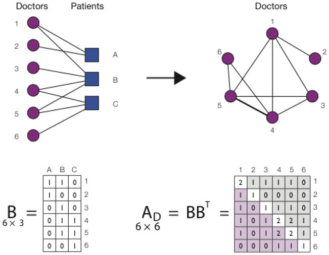
Figure 1.
A schematic illustrating a projection from a two-mode (bipartite) to a one-mode (unipartite) network. Medicare records link each doctor to a number of patients, which naturally leads to a bipartite network consisting of two types of nodes, doctors and patients. An edge can only exist between nodes of different type (a doctor and a patient), and the network is fully described by the (in this case 6 × 3) bipartite adjacency matrix B. A one-mode projection of the doctor-patient network is obtained by multiplying the bipartite adjacency matrix B by its transpose. The resulting symmetric one-mode adjacency matrix A is square in shape (in this case 6 × 6), and its elements indicate the number of patients the two physicians have in common. For example, A(3,4) = 1 shows that physicians 3 and 4 provide care for one common patient (patient B), whereas A(4,5) = 2 shows that physicians 4 and 5 have two patients in common (patients B and C). The diagonal elements of matrix A correspond to the number of patients the given physician provides care for, e.g. A(4,4) = 2 (in other words, physician 1 has degree 2).

