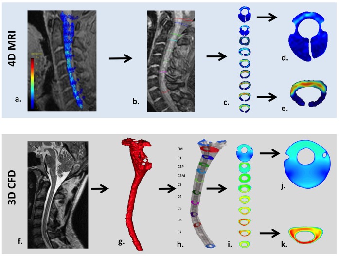
Figure 3. Workflow for 4D PC MRI (top row) and CFD (bottom) methodology in a healthy volunteer.
a) 4D PC MRI velocity vectors superimposed on the coarse 2D anatomy scan. b) Placement of axial planes along the cervical SSS and c) 2D velocity profile visualization of the axial planes. d) Velocity profile example at the FM where ROI image truncation was required due to low velocities and noise in the MRI signal (see Methods for details). e) Velocity profile in the lower cervical SSS where the ROI required less image truncation. f) High resolution anatomical MRI scan used to define the geometry for the CFD simulation. g) 3D rendering of the cervical SSS segmentation before end truncation and geometric smoothing. h) 3D rendering of the smoothed cervical SSS geometry and axial planes where the CFD velocity profiles were observed. i) 2D velocity profile plots for each axial location. j) Velocity profile at the FM showing a larger cross-section than the FM in the 4D PC MRI (compare to d). k) Velocity profile in the lower cervical SSS that compares more favorably in terms of ROI size and shape to that observed in the 4D PC MRI (e).

