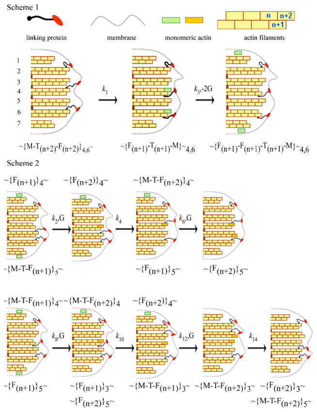
Fig. 8.
Pathway for actin depolymerisation (Scheme 1) and polymerisation (Scheme 2). Scheme 1 Two of the protein linkers, crisscross from the (n+2) to the (n+1) position and pull the membrane towards the cell with rate constant k1, and the same two monomers at position (n+2) escape to the cytoplasm with rate constant k3. Scheme 2. Upper: Monomers bind only to filaments without linkers. A monomer binds at the (n+2) position of the 4th filament after which a protein linker dissociates from the 5th and binds to the 4th pushing the membrane forward. A second monomer then binds to the (n+2) position of the 5th filament. Lower: binding of monomer to filaments with a linker attached. A monomer binds at the (n+1) position (4th filament) and this linker then moves to the adjacent filament pushing the membrane forward. A second monomer binds to the (n+2) position of the 3rd filament and the linker on this filament dissociates and rebinds to the (n+2) position of the 5th filament pushing the membrane forward. The symbols represent G: monomeric actin, M: membrane, F: filament; T: protein linker and the subscript the filament number. The rate constants, k are shown where odd and even subscripts represent depolymerisation and polymerisation.

