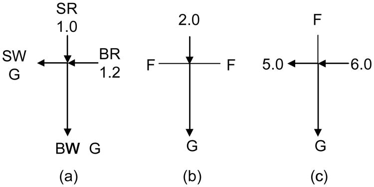
Figure 1.
Voltage configuration. (a) Sample loading, 10 s. (b) Injection, 1 or 2 s. (c) Dispensing/separation, 30 s. The unit of voltage is kV. For hydrodynamic injection, all voltages in (b) were floated for 20 s. BR, buffer reservoir; SR, sample reservoir; BW, buffer waste reservoir; SW, sample waste reservoir; F, floating; and G, ground.

