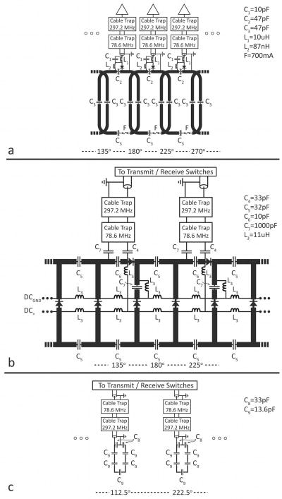
Figure 2.
Partial electrical schematic of the dual-nuclei array. (a) eight-channel sodium receive array. (b) detunable transmit-receive sodium birdcage. (c) transmit-receive proton array. The azimuthal angle is indicated at the bottom of each panel, where 0° is the anterior direction and 180° is the posterior direction. Capacitor and inductor values are +/− 10%.

