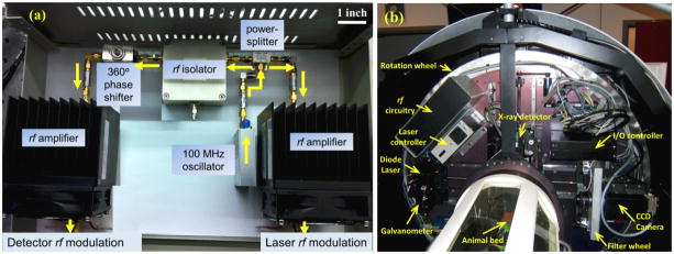
Figure 2.
(a) A photograph of actual implementation of the rf circuitry components for FDPM as represented in Figure 1. Arrows indicate the flow of the rf signal. (b) Photograph shows the rf circuitry from Figure 2(a) mounted within the Siemens Inveon CT scanner along with the rest of the NIRF imaging instrumentation (dotted box from Figure 1). Additional electronics such as galvanometer (for laser scanning), instrumentation controllers, filter wheel (for switching between white-light and emission wavelength), and CT detector are also seen.

