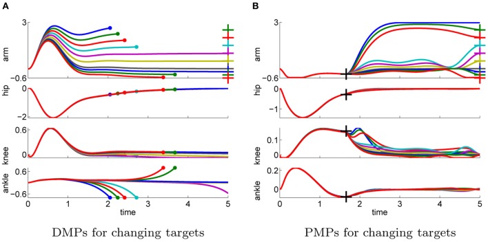
Figure 10.
This figure illustrates the joint angle trajectories (arm, hip, knee, and ankle) of a 4-link robot model during a balancing movement for different final targets of the arm joint (3, 2.5, 2, 1.5, 1, 0.5, 0, −0.2, −0.4, −0.6). The applied policies were learned for a final arm posture of ϕTarm = 0. (A) The valid range of the arm joint using DMPs is ϕTarm ∈ [−0.2, 1]. Large dots in the plot indicates that the robot has fallen. (B) PMPs could generate valid policies for all final arm configurations.

