Abstract
Metallic eye shields have been widely used for near-eye treatments to protect critical regions, but have never been incorporated into treatment plans because of the unwanted appearance of the metal artifacts on CT images. The purpose of this work was to test the use of an acrylic dummy eye shield as a substitute for a metallic eye shield during CT scans. An acrylic dummy shield of the same size as the tungsten eye shield was machined and CT scanned. The BEAMnrc and the DOSXYZnrc were used for the Monte Carlo (MC) simulation, with the appropriate material information and density for the aluminum cover, steel knob and tungsten body of the eye shield. The Pinnacle adopting the Hogstrom electron pencil-beam algorithm was used for the one-port 6-MeV beam plan after delineation and density override of the metallic parts. The results were confirmed with the metal oxide semiconductor field effect transistor (MOSFET) detectors and the Gafchromic EBT2 film measurements. For both the maximum eyelid dose over the shield and the maximum dose under the shield, the MC results agreed with the EBT2 measurements within 1.7%. For the Pinnacle plan, the maximum dose under the shield agreed with the MC within 0.3%; however, the eyelid dose differed by –19.3%. The adoption of the acrylic dummy eye shield was successful for the treatment plan. However, the Pinnacle pencil-beam algorithm was not sufficient to predict the eyelid dose on the tungsten shield, and more accurate algorithms like MC should be considered for a treatment plan.
Keywords: eye shield, electron treatment, Monte Carlo, MOSFET, EBT2
INTRODUCTION
For treatment of lesions involving the eyelid, a shield is used for protection of the underlying globe, including the cornea, conjunctiva, lens, and retina [1–3]. Commercialized eye shields made of lead or tungsten have been used for electron or kilovoltage photon treatment [4–6]. Because the high Z material eye shield induces backscattered dose enhancements on the upstream eyelid, coating the eye shield with a plastic material or another thin aluminum cover assembly has been suggested and successfully used to reduce the backscattering. When a dose of 1.00 Gy with a 6-MeV electron beam was delivered to a depth of maximum dose (dmax) of open field, the 2-mm-thick tungsten shield with a 0.5-mm aluminum cover was reported to give a backscattered dose of 1.03 Gy at the under surface of the eyelid [5].
In clinics, the eye shield is used in two ways for eyelid treatment. The simplest method is to design the electron treatment plan based on the patient's CT images, with the shield itself not being incorporated into the planning. This is done in conventional single-port treatment in which the patient is treated with the eye shield positioned on the eye. Usually, the point dose is measured before the treatment to confirm the target dose. This has drawbacks in that the planner has no information on the dose distribution that the metallic eye shield creates. The organ protection for the lens, e.g., is presumed based on the dosimetry data measured once in a while. Another approach is for the planner to measure the dimensions of the eye shield, draw the shield contour covering the eyeball on each CT image slice, and apply a density override for the dose calculation. Although more advanced than the first method, in the latter method the dose distribution of the posterior, beneath the contoured eye shield, still does not reveal the eyelid dose, which is very often the most concerning point of treatment.
These unsatisfactory approaches are attributed to the fact that the metallic eye shield makes indiscernible artifacts on the patient CT images. In the field of brachytherapy, metal applicators are used that also cause artifacts on X-ray and CT images. However, that problem is solved by adopting available CT dummy applicators to obtain artifact-free images for the applicators and the patients [7]. The same idea could be applied to the eye shield. An acrylic eye shield made with the same dimensions as the metallic eye shield can be positioned on the target area of the patient, and the CT images acquired. For the treatment plan, the regions of interests (ROIs) corresponding to the eye shield are delineated, and CT numbers or densities are modified appropriately for each part of the shield, then the dose calculation is executed. This idea is simple, but could be very useful for electron treatment near the region of the eye. In this paper, we investigate the possibility of using the dummy eye shield for an electron treatment plan on the Pinnacle (Philips, version 8.0 m) with the Hogstrom pencil-beam algorithm [8, 9], and evaluate the dose calculation accuracy with the measurements and Monte Carlo (MC) simulation.
MATERIALS AND METHODS
Eye shield, dummy eye shield and CT scan
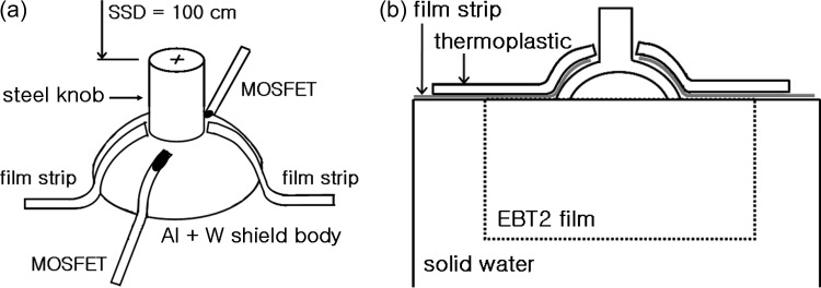
A 2-mm-thick curved tungsten eye shield (Radiation Products Design, Inc., MN, USA) was used as a sample, over which a 0.5-mm thick aluminum cover was assembled to reduce the backscatter radiation. The density of the tungsten shield was 17.0 g/cm3, and that of the aluminum cover was 2.718 g/cm3, based on product specifications. The material information for the knob was unclear, except that it was steel, so we assumed the material to be stainless steel and assigned it a density of 7.9 g/cm3. An acrylic, dummy shield was machined with as close to the same physical dimensions as the eye shield as possible. Because the dummy shield was to be inserted under the eyelid, the surface was made very smooth so as not to hurt the patient's eye. For the eyelid simulation, a 3-mm thick thermoplastic sheet was shaped to cover the eye shield (Fig. 1). Mounted on solid water slabs (Gammex, Middleton, WI, USA), CT images were acquired with 0.5 mm × 0.5 mm resolution and a slice thickness of 1.25 mm.
Fig. 1.
An experimental setup. (a) Two EBT2 film strips on the right and left sides, two MOSFET detectors on the superior and the inferior sides, covered by 3-mm thickness thermoplastic for an eyelid simulation. The beam isocenter is at the top center of the steel knob. (b) A vertical EBT2 film is sandwiched with solid phantoms under the eye shield for the dose distribution measurements.
EBT2 and MOSFET measurements
An electron beam of 6-MeV from a Varian 21-EX accelerator (Varian Medical Systems, Palo Alto, CA, USA) was used throughout the study. The field was defined with the 10 × 10 cm2 electron applicator, and the distance from the beam source to the top of the eye shield knob (SSD) was set at 100 cm (Fig. 1a). The irradiation was arbitrarily fixed at 200 monitor units (MU). To measure the radiation dose delivered to the inner surface of the eyelid, two EBT2 film strips (International Specialty Products, Wayne, NJ, USA), approximately 3 mm in width, were inserted between the phantom eyelid and the tungsten shield body at both left and right positions. EBT2 films are newly-released radiochromic films replacing the EBT (which is no longer available), and the film characteristics are described in recent reports [10–12].
To confirm the film measurements, two metal oxide semiconductor field effect transistor (MOSFET, model TN-502RD; Thomson and Nielson, Ottawa, Canada) detectors were also placed on the eye shield in superior-inferior (SI) positions. The space for MOSFETs was prepared during thermal fabrication of the eyelid replacement. The specifications, including the physical dimensions of the MOSFET, have been described previously [13–16]. The MOSFET and the film measurements were repeated three times and averaged. An EBT2 film was also inserted vertically between solid water slabs under the eye shield to measure the dose distribution below the shield (Fig. 1b).
Measurement calibration
The accelerator output was checked for the reference condition of 6 MeV and a 10 × 10 cm2 field size at SSD = 100 cm using a plane parallel ionization chamber, PPC40 with DOSE1 electrometer (Scanditronix-Wellhofer), and then both the MOSFETs and the EBT2 films were calibrated. MOSFET calibration was performed at the depth of the maximum dose to convert the induced voltage readings to the dose. For the net optical density of the EBT2 films, the exposed films were scanned with a VXR-16 film digitizer (VIDAR Systems Corporation, Herndon, VA, USA), followed by the scanner uniformity correction, then analysed with DoseLab, a freeware for film dosimetry [17]. Film pieces for the calibration curve were exposed for dose ranges ≤2.5 Gy.
MC simulation
The EGSnrc-based BEAMnrc and the DOSXYZnrc were used for the MC simulation [18, 19].With the 10 × 10 cm2 6 MeV electron beam as a reference condition, the accelerator modeling was performed such that the R50 and the Rp (electron practical range) of the simulated and the measured percentage depth doses (PDD) agreed to within 1 mm by adjusting the starting electron energy [20, 21]. The final selected primary input energy was 6.72 MeV.
For the MC simulation of the eye shield under irradiation, the CT images of the dummy shield covered with the eyelid phantom on the solid water slabs were used. After cooling, the thermoplastic for the eyelid phantom was separated by an air gap of less than 1 mm from the underlying eye shield. The CT images have blurred pixel values due to a partial volume effect, resulting in less clear material boundaries and considerable CT numbers, even for the air present between different materials. As our simulation should consider mm dimensions, the CT numbers for the air gap were zeroed as much as possible without disturbing the phantom material boundaries.
Because the real eye shield consisted of a steel knob, a thin aluminum cover, and a tungsten body, the dummy shield image should have been identified for each part and assigned with the respective material information for MC simulation. However, the CT numbers of the acrylic dummy shield were in a range similar to those of the tissue-equivalent eyelid phantom; therefore, it was not straightforward to differentiate both of them clearly on the CT images. By considering the physical dimension of the eye shield and the pixel size of the images, the CT numbers of the aluminum cover, the shield knob and the shield body areas were arbitrarily modified with, e.g., 2700, 7900 and 17 000, respectively. The CT conversion package for DOSXYZnrc, ctcreate, was used to consider the appropriate material information and density for each CT number in the MC simulation. For example, based on the modified CT numbers, STEEL521ICRU with density range from 2.718–7.9 g/cm3 was assigned to CT numbers between 2700 and 7900, and W521ICRU with density range from 7.9–17.0 g/cm3 was assigned to CT numbers between 7900 and 17 000. The eyelid phantom and the solid water slabs were regarded as water.
Although the thickness of the eye shield and the eyelid phantom was 2–3 mm, the resolution of the CT images was modified from a 0.5 mm × 0.5 m axial resolution to 1.0 × 1.0 mm2 for a reasonable simulation time with reasonable statistical uncertainties. No range rejection was used and the ECUT and the PCUT were set at 0.521 MeV and 0.01 MeV, respectively. The simulation result, *.3ddose, which is the dose per incident particle, was rescaled into the absolute dose based on the reference condition, and was transferred into the Pinnacle for a convenient evaluation.
Pinnacle plans
Using the same CT images as in the MC simulation, the same electron treatment plan was designed on the Pinnacle (‘Pinnacle_CT#’ plan). Because the CT image has artificially enhanced CT numbers for the eye shield, an adequate CT to density table was created in the Pinnacle for the proper conversion into densities, such that 2.718 g/cm3 for aluminum, 4.2 g/cm3 for steel, and 17.0 g/cm3 for tungsten were considered, respectively. Pinnacle adopts the Hogstrom pencil-beam (PB) algorithm for the electron beam dose calculation [8, 9].
In the planning, the delineation of the ROIs and the density override is the standard approach for tackling the high-density materials. Incidentally, the eye shield has a 0.5-mm-thick aluminum cover to reduce the backscattered dose. Therefore, it is required to check the dose calculation results based on the ROI delineation and the density override function. Moreover, it is interesting to compare the dose difference from a pencil-beam algorithm with and without the aluminum cover. If the difference is negligible, the planner does not need to consider the thin aluminum cover, taking less time for planning. For this purpose, two more Pinnacle plans were produced. The first plan included only the tungsten and the steel knob parts of the eye shield but not the aluminum cover (“W ROI” plan). The eye shield was contoured by a drawing tool using the usual planning window/level settings. Then, the densities of the eye shield parts corresponding to the tungsten and the steel were changed to 17.0 g/cm3 and 4.2 g/cm3, respectively. Because the image resolution was 0.5 mm × 0.5 mm, the tungsten part of the 2-mm-thickness could be drawn easily. For the second plan, the aluminum cover of 0.5-mm thickness (a single pixel thickness) on the CT image, was contoured outward from the tungsten regions and the density was changed to that of aluminum (2.718 g/cm3) (‘W & Al ROIs’ plan). Drawing ROIs took relatively less labor because the eye shield dimensions were small, extending over 20 slices of the 1.25-mm thickness.
RESULTS AND DISCUSSION
MC, film and Pinnacle results
Figure 2 shows the following: (a) the MC simulation results with a 1-mm resolution; (b) the EBT2 film results; and (c) the Pinnacle calculation results, at the isocenter plane. All results were obtained by 200-MU deliveries. Due to the setup limitation, slightly asymmetric results on both left and right sides were obtained. However, as we are concerned with comparing the calculation results of different planning methods, we discuss hereafter only the results for the right half. For the MC results with the beam isocenter set at the top of the shield knob (Fig. 2a), the dose along the curved inner eyelid just above the eye shield was 197.7 ± 10.0 cGy for ROI volumes of 0.01 cm3 and ∼ 6 mm length. A similar-sized ROI dose at the exterior surface of the eyelid was 170.8 ± 9.1 cGy. Below the eye shield block, reduced dose distributions were established to protect the critical organs. After passing the minimum central axis dose of 11.7 cGy at a depth of 2 mm, the dose increased up to 47.3 cGy at 14 mm due to lateral scatter contribution. Laterally, from the sharp surface irregularities, the well-known high-dose regions off the metallic shields appeared [22], and the maximum point dose in the solid water phantom below the eye shield was 196.1 cGy. It was noted that the maximum dose in the solid phantom was the same as that of the inner eyelid dose within the uncertainty range mentioned earlier.
Fig. 2.
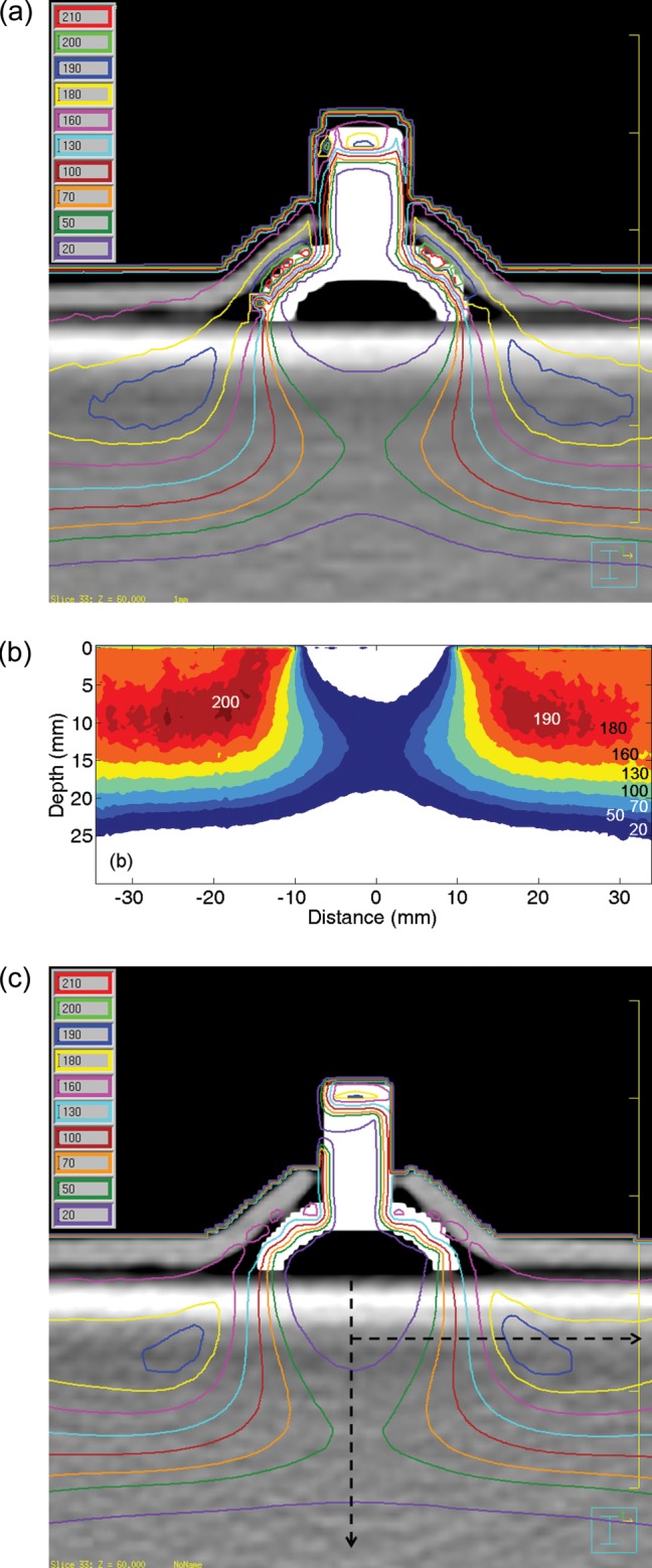
(a) MC simulation results with the modified CT images at the isocenter plane. (b) The EBT2 film results below the eye shield. Legends for dose values are added. (c) Pinnacle plan results with the same modified CT images. Analysis was conducted for the right half, assuming symmetric.
Figure 2b represents the EBT2 film dosimetry results below the eye shield. The results were similar to the MC results, and the maximum phantom dose was 197 cGy at the point lateral of the eye shield. The CT images used for the MC simulation were also used for the Pinnacle calculation, and the results are shown in Fig. 2c. The white image of the eye shield is due to the enhanced CT numbers for its component materials. The curved eyelid dose at the interface with the eye shield was 159.6 ± 4.5 cGy, which is very different from the MC calculation. In contrast to the eyelid dose, the maximum phantom dose was 196.6 cGy at the point within 5.2 mm of the MC maximum dose position.
Comparison of depth and lateral profiles
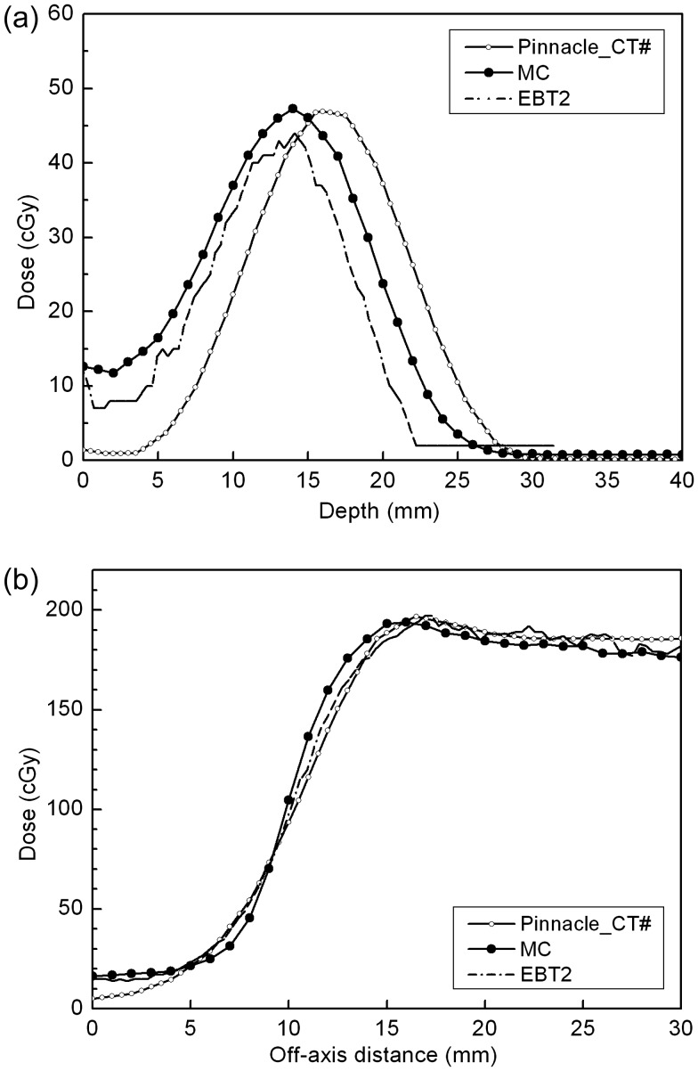
Along the two dashed lines in Fig. 2c, both (i) the central and (ii) the off-axis lateral dose profiles for the MC/Film/Pinnacle are compared in Fig. 3. The off-axis lateral profiles were obtained at a 6-mm depth from the phantom surface, and it was the line containing the point of maximum phantom dose in the Pinnacle. In the case of central axis depth profiles, MC and EBT2 showed the same maximum depth (d = 14 mm from the phantom surface) with maximum doses differing by 3.3 cGy. On the other hand, the Pinnacle results showed underestimation just below the eye shield and extended to a deeper depth than the MC and the film results. In Fig. 2c, the dose line of 20 cGy reflects this behavior of the Pinnacle, in which the degree of the concavity is insignificant compared to the MC and the EBT2 at the central axis. The shift of the depth dose in the Pinnacle might be attributed to the small-angle scattering mechanism of the Hogstrom pencil-beam (PB) algorithm, in which the lateral scattering is not considered to faithfully cover the dose distribution after passing the tungsten shield [8, 9]. However, the shift is less than 2 mm and considered to be negligible in the clinical application. In the investigated region of 30 mm in the lateral direction, all three lateral profiles of the MC/EBT2/Pinnacle were in good agreement with each other (within 5%/2.0 mm) (Fig. 3b). The Pinnacle calculation can be said to show acceptable accuracy for the dose distribution below the tungsten eye shield.
Fig. 3.
(a) Central depth profiles and (b) Lateral profiles from the modified CT-based Pinnacle plan (Pinnacle_CT#), MC simulation, and EBT2 film measurements. Along the vertical and the horizontal dashed lines in figure 2(c), profiles were extracted.
Eyelid dose calculations and measurements
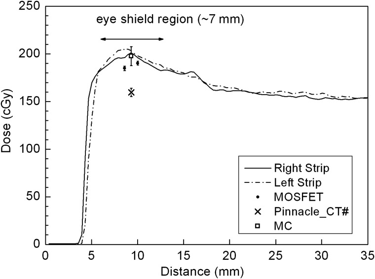
All the calculations (MC and Pinnacle) and measurements (left/right EBT2 film strips and superior/inferior MOSFETs) for the eyelid interface are presented in Fig. 4. The film strip results obtained for both the left and the right sides of the eye shield are the average values from three exposures. Both maximum doses of the film strips have < 2.5% standard deviation. As stated earlier, the MC and the Pinnacle results were calculated using a long, small ROI along the inner eyelid. Two MOSFET readings from the SI direction, in which the data coordinates are arbitrary, were added for comparison. Except for the Pinnacle (159.6 ± 4.5 cGy), the other three results seem to agree with each other within 5% as follows. Considering the slightly different thickness of the eyelid replacement on both sides, the film strips irradiated between the eyelid and the eye shield showed similar dose distributions. The dose range along the curved path of the eye shield, which extends ∼7 mm, is 180–200 cGy. Therefore, the overall dose at the interface between the eyelid and the eye shield can be said to be > 180 cGy on the shield block.
Fig. 4.
Dose comparison at the inner surface of the eyelid. The MC simulation result shows good agreement with the right EBT2 strip (also with the left EBT2) and superior-inferior MOSFET measurements. The Pinnacle PB calculations on the modified CT images (Pinnacle_CT#) underestimate the dose by 20%.
In the case of the MOSFET, readings taken at two positions in the SI direction were 184.8 ± 2.41 cGy and 190.3 ± 2.09 cGy, respectively, which are 6.5% and 3.7% lower compared to MC calculations. Considering these measurements were obtained on the curved shield surface, the results are reasonable. The silicon chip with an active area of ∼0.04 mm2 in the MOSFET detector is covered with an epoxy bulb, ∼7 mm in length. Therefore, the exact positions of the MOSFETs on the curved eye shield were not identified. The MOSFET direction relative to the irradiated beam has been reported to affect the detector readings [14–16]. The directional dependence of the MOSFET can be divided into two parts as follows: the axial rotation in the plane perpendicular to its length direction; and the tilt along the length direction. In the axial rotation <45o, about a 3% response variation relative to 0o was reported. In the case of tilting by 45o with 9 MeV, which is the situation on the curved eye shield except the energy, the detector reading was reported to be underestimated by 13% [16]. Another factor to be considered is that the epoxy bulb encapsulating the silicon chip of the MOSFET is estimated to be equivalent to a 1.8-mm water thickness, which means that the effective measurement depth of the MOSFET is 4.8 mm rather than the 3-mm eyelid thermoplastic. This increase of the depth in the build-up region causes up to 5% more dose for 6-MeV electrons. Therefore, taking into account the underestimation of the dose due to the oblique incidence of the beam and the increased response because of the effectively additional buildup, the MOSFET measurements on the eye shield agree with the MC calculations within 5%.
Comparison of Pinnacle calculations
The same CT images as prepared for the MC simulation were used for Pinnacle calculations, i.e. the CT numbers of the eye shield were assigned to appropriate material densities. Also, the in-between air gaps, though small in volume, were preserved to simulate the reality of the shield and the eyelid phantom. However, direct modification of the CT images can be cumbersome. For example, the scanned CT numbers for the acrylic dummy eye shield were not homogeneous, hindering the simple threshold approach for changing the CT numbers above a desired value, thus requiring point-by-point modifications for some island-like regions.
One of the favored approaches using the suggested dummy shield is to rely on the contouring and density override function on the RTPS, and moreover the contouring of the tungsten and steel knob only, without the 0.5-mm aluminum cover. The result is shown in Fig. 5. The maximum dose in the solid water phantom was 202.8 cGy at a similar position as in the previous plans and the eyelid dose was 161.7 ± 6.8 cGy, which are nearly the same results as those obtained from the Pinnacle plan calculated using the modified CT images. With the additional aluminum contouring and density override, the plan also showed very similar results, such that the maximum dose in the phantom was equal at the same position and the eyelid dose was 164.6 ± 5.0 cGy.
Fig. 5.
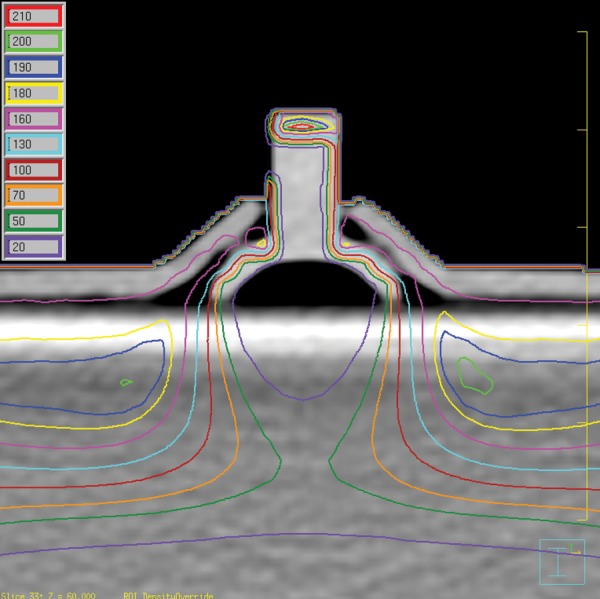
Pinnacle plan results by the contouring and the density override for the tungsten shield and the steel knob. Here, the 0.5-mm thickness of the aluminum cover assembly was not considered.
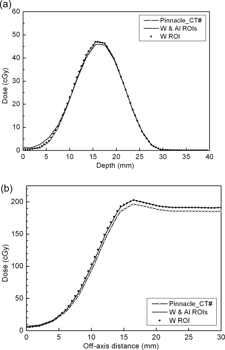
Figure 6 shows (a) the central axis and (b) the d = 6 mm depth lateral profiles on the Pinnacle for three CT images (the modified CT, the tungsten/steel knob contoured CT, and the additional aluminum contoured CT). Neither of the contour-based Pinnacle results show any meaningful differences and agree with the modified CT case within 3%. The fact that all the plans made on the Pinnacle are similar allows us to conclude that the contouring and the resultant density override of the tungsten shield and steel knob are sufficient for the electron eye shield planning on the Pinnacle without needing to consider the thin aluminum cover. However, one should note that the calculated eyelid dose is still underestimated by approximately 20%. The electron pencil beam algorithm, as in Pinnacle, is known to have poor ability to cope with inhomogeneities [8, 23]. The eye shield density, which is 17 times greater than water, can be an extreme case for which the problem is amplified, and which leads to the poor predictability of the eyelid dose in the region immediately adjacent to the eye shield.
Fig. 6.
(a) Pinnacle central depth profiles for the modified CT (Pinnacle_CT#), contouring of the tungsten shield/steel knob/aluminum cover and density override CT (W & Al ROIs), and the aluminum cover–neglected CT (W ROI). (b) Lateral profiles for the same CT data sets. Consideration of the thin aluminum cover does not make any practical differences to the Pinnacle calculation.
Dose prescription with and without the eye shield
A few representative point doses are summarized in Table 1. The insufficient accuracy of the pencil beam algorithm for the extremely inhomogeneous problems calls for an enhanced calculation modality such as the MC simulation used herein. The idea of a dummy shield is so simple that it is difficult to believe that a protective eye shield has not been considered in treatment planning before. The impact of using a dummy eye shield is not limited to dosimetric evaluations. Clinically, the dummy shield can eliminate the ambiguity of the prescription dose by clarifying the planning environment. Based on clinical outcomes, most reports have recommended 25–30 Gy for local control of a MALT lymphoma [1–3], with a lens shield used during treatments after traditional open beam planning. It is not clear whether the prescribed dose is the nominal calculation in the planning or the measured dose from a dosimetry check. Presumably, due to the very good radiation response of MALT lymphomas, relatively less attention seems to have been paid to the dose accuracy. The dose prescription uncertainty is not confined to MALT lymphomas, but applies to all treatments with an eye shield block. The dummy eye shield approach is a promising solution for near eye treatments, not only for correct evaluation of the treatment plan, but also for an unambiguous dose prescription. With a CT-compatible dummy eye shield, we can easily improve the calculation accuracy of treatment planning.
Table 1.
Comparison of point doses for plans and measurement (cGy)
| Plan | Solid slab maximum dose (Diff)a | Central axis maximum dose | Eyelid dose (Diff) |
|---|---|---|---|
| MC | 196.1 | 47.3 | 197.7 ± 10 |
| EBT2 | 197 (+ 0.5%) | 44 | 201d (+ 1.7%) |
| Pinnacle_CT#b | 196.7 (+ 0.3%) | 46.9 | 159.6 ± 4.5 (– 19.3%) |
| Pinnacle_W ROIc | 202.8 (+ 3.4%) | 47.0 | 161.7 ± 6.8 (– 18.2%) |
aDiff = percentage of difference relative to the MC results.
bPinnacle_CT# = Pinnacle plan based on the modified CT images.
cPinnacle_W ROI = Pinnacle plan based on the contouring and density override for the tungsten shield and steel knob.
dThis eyelid dose is the maximum dose taken from EBT2.
CONCLUSION
An acrylic dummy eye shield was successfully used for electron treatment planning, in which the metal artifact problem was solved, and which showed that the patient CT images with the eye shield could be incorporated. The Pinnacle with the Hogstrom pencil-beam algorithm was used and compared with the MC calculation and measurements. In Pinnacle, the contours of the tungsten shield and the steel knob were delineated for the treatment plan, and the thin aluminum cover assembly did not introduce any improvements for the calculation accuracy. The dose calculation accuracy over the metallic eye shield was evaluated to be different from that under the shield. The calculated dose distribution under the shield showed a clinically acceptable accuracy with the MC simulation and the EBT2 film measurements. However, the eyelid dose over the tungsten shield was underestimated by 20%. Contrary to the dose distribution under the eye shield, the eyelid dose by the Pinnacle should only be used for a rough guide to the dose distribution, and should be followed by the dosimetric check for the patient treatment. More exact dose calculation algorithms such as the Monte Carlo simulation adopted in this study are strongly suggested for the plan using the tungsten eye shield.
FUNDING
This work was supported by a Korea Science and Engineering Foundation (KOSEF) grant funded by the Korean Government (MOST) (No. M20706000007-07M0600-00710).
REFERENCES
- 1.Tomita N, Kodaira T, Tachibana H, et al. Favorable outcomes of radiotherapy for early-stage mucosa-associated lymphoid tissue lymphoma. Radiother Oncol. 2009;90:231–5. doi: 10.1016/j.radonc.2008.12.004. [DOI] [PubMed] [Google Scholar]
- 2.Yamashita H, Nakagawa K, Asari T, et al. Radiotherapy for 41 patients with stages I and II MALT lymphoma: a retrospective study. Radiother Oncol. 2008;87:412–7. doi: 10.1016/j.radonc.2008.03.012. [DOI] [PubMed] [Google Scholar]
- 3.Zhou P, Ng AK, Silver B, et al. Radiation therapy for orbital lymphoma. Int J Radiat Oncol Biol Phys. 2005;63:866–71. doi: 10.1016/j.ijrobp.2005.03.005. [DOI] [PubMed] [Google Scholar]
- 4.Baker CR, Luhana F, Thomas SJ. Absorbed dose behind eye shields during kilovoltage photon radiotherapy. Br J Radiol. 2002;75:685–8. doi: 10.1259/bjr.75.896.750685. [DOI] [PubMed] [Google Scholar]
- 5.Shiu AS, Tung SS, Gastorf RJ, et al. Dosimetric evaluation of lead and tungsten eye shields in electron beam treatment. Int J Radiat Oncol Biol Phys. 1996;35:599–604. doi: 10.1016/s0360-3016(96)80024-1. [DOI] [PubMed] [Google Scholar]
- 6.Weaver RD, Gerbi BJ, Dusenbery KE. Evaluation of eye shields made of tungsten and aluminum in high-energy electron beams. Int J Radiat Oncol Biol Phys. 1998;41:233–7. doi: 10.1016/s0360-3016(97)00905-x. [DOI] [PubMed] [Google Scholar]
- 7.Nag S, Cardenes H, Chang S, et al. Proposed guidelines for image-based intracavitary brachytherapy for cervical carcinoma: report from Image-Guided Brachytherapy Working Group. Int J Radiat Oncol Biol Phys. 2004;60:1160–72. doi: 10.1016/j.ijrobp.2004.04.032. [DOI] [PubMed] [Google Scholar]
- 8.Hogstrom KR, Mills MD, Almond PR. Electron beam dose calculations. Phys Med Biol. 1981;26:445–59. doi: 10.1088/0031-9155/26/3/008. [DOI] [PubMed] [Google Scholar]
- 9.Starkschall G, Shiu AS, Bujnowski SW, Hogstrom KR, et al. Effect of dimensionality of heterogeneity correction on the implementation of a three-dimensional electron pencil beam algorithm. Phys Med Biol. 1991;36:207–27. doi: 10.1088/0031-9155/36/2/006. [DOI] [PubMed] [Google Scholar]
- 10.Arjomandy B, Tailor R, Anand A, et al. Energy dependence and dose response of Gafchromic EBT2 film over a wide range of photon, electron, and proton beam energies. Med Phys. 2010;37:1942–7. doi: 10.1118/1.3373523. [DOI] [PubMed] [Google Scholar]
- 11.Hartmann B, Martisikova M, Jakel O. Homogeneity of Gafchromic EBT2 film. Med Phys. 2010;37:1753–6. doi: 10.1118/1.3368601. [DOI] [PubMed] [Google Scholar]
- 12.Richley L, John AC, Coomber H, et al. Evaluation and optimization of the new EBT2 radiochromic film dosimetry system for patient dose verification in radiotherapy. Phys Med Biol. 2010;55:2601–17. doi: 10.1088/0031-9155/55/9/012. [DOI] [PubMed] [Google Scholar]
- 13.Soubra M, Cygler J, Mackay G. Evaluation of a dual bias metal oxide-silicon semiconductor field effect transistor detector as radiation dosimeter. Med Phys. 1994;21:567–72. doi: 10.1118/1.597314. [DOI] [PubMed] [Google Scholar]
- 14.Chuang CF, Verhey LJ, Xia P. Investigation of the use of MOSFET for clinical IMRT dosimetric verification. Med Phys. 2002;29:1109–15. doi: 10.1118/1.1481520. [DOI] [PubMed] [Google Scholar]
- 15.Bloemen-van Gurp EJ, Minken AW, Mijnheer BJ, et al. Clinical implementation of MOSFET detectors for dosimetry in electron beams. Radiother Oncol. 2006;80:288–95. doi: 10.1016/j.radonc.2006.07.002. [DOI] [PubMed] [Google Scholar]
- 16.Manigandan D, Bharanidharan G, Aruna P, et al. Dosimetric characteristics of a MOSFET dosimeter for clinical electron beams. Phys Med. 2009;25:141–7. doi: 10.1016/j.ejmp.2008.11.003. [DOI] [PubMed] [Google Scholar]
- 17.Childress NL, Vantreese R, Kendall R. DoseLab v.4.0.0: dose comparison software package for medical physics. Houston: The University of Texas, MD: Anderson Cancer Center; 2004. [Google Scholar]
- 18.Kawrakow I. Accurate condensed history Monte Carlo simulation of electron transport. I. EGSnrc, the new EGS4 version. Med Phys. 2000;27:485–98. doi: 10.1118/1.598917. [DOI] [PubMed] [Google Scholar]
- 19.Rogers DW, Faddegon BA, Ding GX, et al. BEAM: a Monte Carlo code to simulate radiotherapy treatment units. Med Phys. 1995;22:503–24. doi: 10.1118/1.597552. [DOI] [PubMed] [Google Scholar]
- 20.Chow JC, Grigorov GN. Monte Carlo simulation of backscatter from lead for clinical electron beams using EGSnrc. Med Phys. 2008;35:1241–50. doi: 10.1118/1.2874552. [DOI] [PubMed] [Google Scholar]
- 21.Verhaegen F, Mubata C, Pettingell J, et al. Monte Carlo calculation of output factors for circular, rectangular, and square fields of electron accelerators (6-20 MeV) Med Phys. 2001;28:938–49. doi: 10.1118/1.1373402. [DOI] [PubMed] [Google Scholar]
- 22.Khan FM. The Physics of Radiation Therapy. 3rd edn. Philadelphia, PA: LWW; 2003. [Google Scholar]
- 23.Ding GX, Cygler JE, Yu CW, et al. A comparison of electron beam dose calculation accuracy between treatment planning systems using either a pencil beam or a Monte Carlo algorithm. Int J Radiat Oncol Biol Phys. 2005;63:622–33. doi: 10.1016/j.ijrobp.2005.06.016. [DOI] [PubMed] [Google Scholar]


