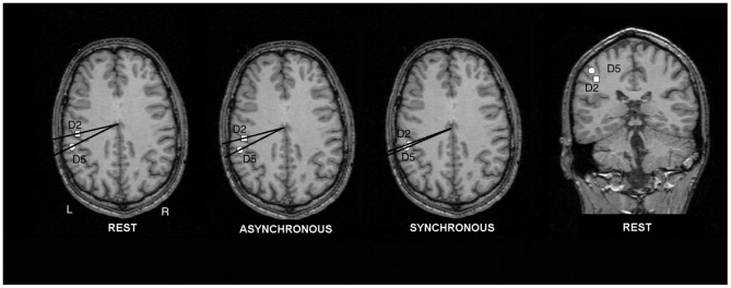
Figure 4. Dipole localizations of the SEFs for one representative subject overlaid onto an axial MRI slice.
The positions of the dipole sources are specified in polar coordinates. The squares depict the cortical representations of D2; the circles show the representations for D5. Note the differences in polar angle Δφ between rest, asynchronous, and synchronous brushing, pointing to a decrease of the cortical distance in the synchronous brushing condition. For verification of dipole sources a coronal slice (rest condition) is depicted.

