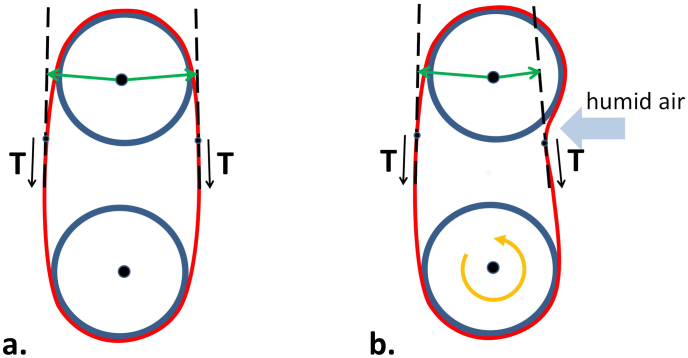
Figure 6. Schematic of the humidity induced bending mechanism.
(a) The configuration is symmetric about a vertical axis. The lever arms (green) are of equal length, and the net torque on the top wheel due to tension in the film is zero. (b) Due to the humidity-induced bend, the configuration is no longer symmetric. Lever arm on the right in top wheel is shorter; net torque on top wheel due to tension in the film gives rise to CW rotation. (The humidity induced bend has been exaggerated to aid the illustration.)

