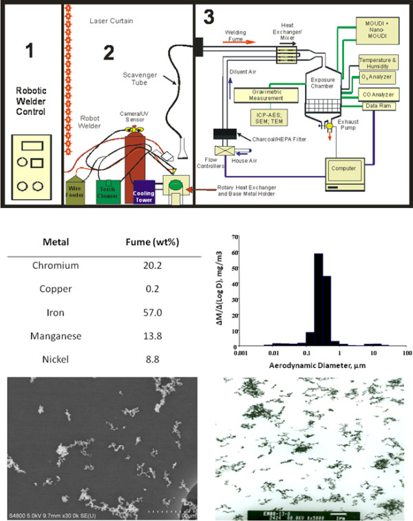
Figure 1.

Characterization of the welding fume exposure. Diagram of the NIOSH welding inhalation system (upper panel): 1) Computer control and power source, 2) robotic welder and accompanying hardware necessary for fume generation and 3) exposure chamber and characterization devices. The middle left panel represents the metal content of the GMA-SS fume. The middle right panel shows the particle size distribution of the generated fume (M = mass concentration and D = aerodynamic diameter). The bottom panels show a scanning electron micrograph (left) and transmission electron micrograph (right) of the welding fume.
