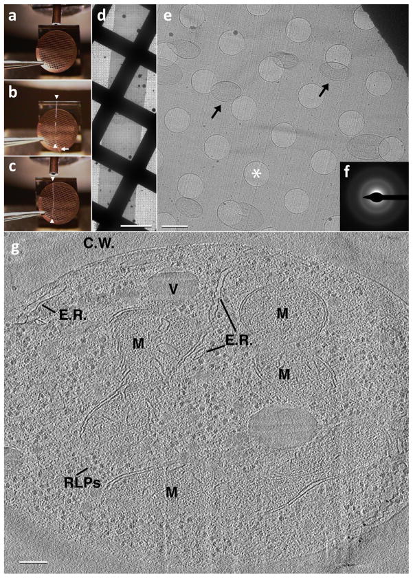
Figure 3.
Imaging of vitreous sections by cryo-electron microscopy. (a) An EM grid is placed at the diamond knife-edge using tweezers with a bent tip. (b) A ribbon of vitreous sections (white arrowheads) is guided over the EM grid using an eyelash (white arrow) attached to a wooden dowel. (c) Once the ribbon of vitreous sections is of suitable length (white arrowheads), approximately the diameter of the EM grid, an electrostatic generator is switched from the discharge mode to the charge mode, causing the ribbon to attach to the EM grid. (d) A low magnification image showing the ribbon of vitreous sections after electrostatic charging. Scale bar: 50 μm. (e) A medium magnification micrograph showing a vitreous section from within the ribbon. Note that the section is smooth and relatively flat with no apparent mechanically induced damage as is often seen with stamping/pressing techniques. S. cerevisiae cells can be seen scattered throughout the vitreous section (black arrows). Holes within the C-Flat EM grid can be seen and one such is denoted with a white asterisk. Scale bar: 2 μm. (f) A selected area diffraction pattern confirming vitreous ice. (g) A 50 Å thick slice through a reconstructed tilt series from a 500 Å thick vitreous section of an S. cerevisiae cell: C.W. – Cell Wall, V – Vacuole, M – Mitochondrion, E.R. – pieces of Endoplasmic reticulum, RLPs – Ribosome-like particles. Scale bar: 1000 Å.

