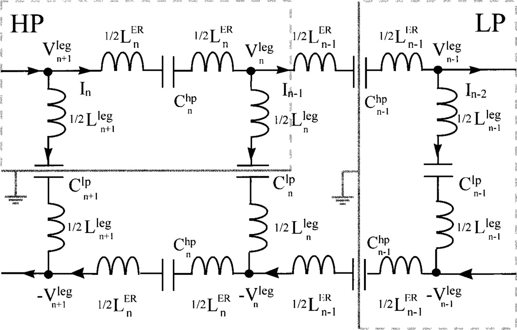
Figure 1.
A circuit model for a band-pass birdcage coil design. The Ln and are the effective inductances of the nth leg and ER segment, respectively; and are the capacitances on the nth leg and ER segment, respectively; and In is the current intensity in the nth loop. The voltage at the end point of the nth leg is . When is given, the virtual ground is assumed at the middle of the legs (see the left box labeled HP); if is known, a virtual ground is inserted at the middle of the (n − 1)th ER segments on both ER planes (see the right box labeled LP).

