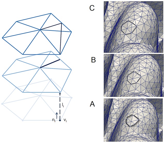
Figure 3. An example of three consecutive accretive growth steps.
(A–C) Accretive growth steps; vertex vi represents a simulated corallite. The new layer is constructed along the direction of normal vector ni of the vertex vi. A, B and C are three consecutive growth steps where triangles are inserted once the surface of the object increases.

