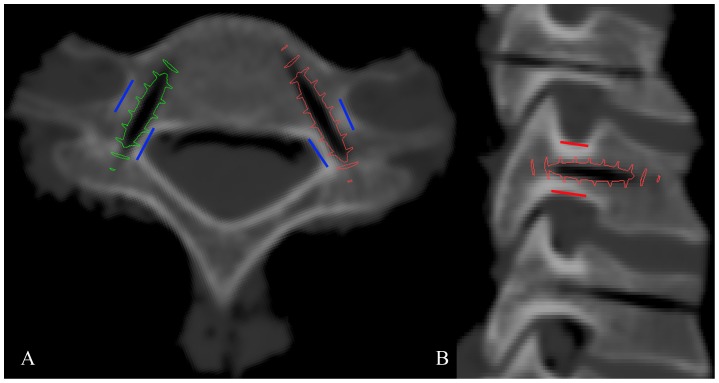
Figure 4. Accuracy evaluation with screw simulation insertion in the axial (A) and sagittal (B) planes.
The blue lines in Figure 4A are the border of cervical pedicle in axial plane. The structures inside and outside the blue lines are vertebral canal and vertebral artery, respectively. And the red lines in Figure 4B are the border of cervical pedicle in sagittal plane. The structures upper and lower the red lines are foramen intervertebrale. A pre-designed 3D screw model (3.5 mm in diameter), which aligned with the pin tract of the 3D model of group2, was imported into Mimics to simulate the screw insertion. The screw positions were graded according to the distance between the screw thread and the border of pedicle cortex.

