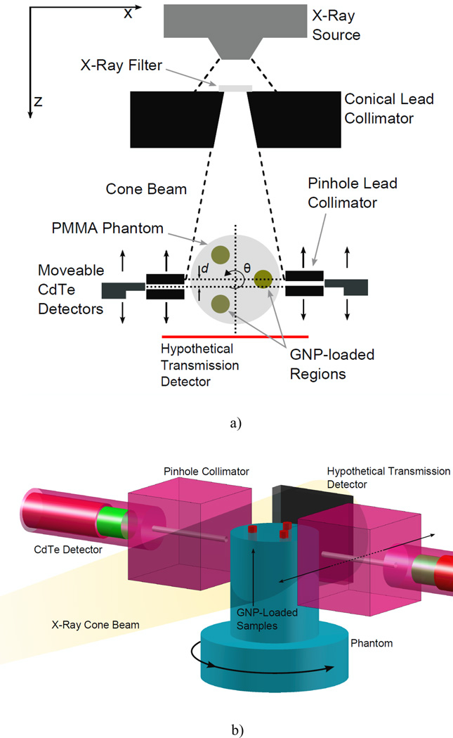
Figure 1.
Experimental setup for benchtop XFCT. (a) Cross-sectional view in the imaging plane. The angle of the conical collimator was 11.4°, with front and back opening diameters of 1 and 2 cm, respectively. The center of the phantom was roughly 8 cm from the collimator surface (14.5 cm from exit window of source). Each detector was positioned behind a 2.5 mm-diameter lead pinhole collimator that was placed 0.75 cm away from the phantom surface. (b) 3-D view of the detector and imaging phantom setup. A 3-cm-diameter polymethyl methacrylate phantom containing three GNP-loaded regions is irradiated by a cone beam of filtered x-rays. The gold Kα fluorescence and Compton-scattered photons are detected by two CdTe detectors placed at 90° relative to the beam central axis. The imaging sinogram S(q, d) is assembled via successive rotations of the phantom and translations of the fluorescence detectors. Although not used in this study, the geometry is compatible with standard transmission imaging, allowing simultaneous acquisition of a transmission CT image.

