Abstract
Purpose: X-ray scatter results in a significant degradation of image quality in computed tomography (CT), representing a major limitation in cone-beam CT (CBCT) and large field-of-view diagnostic scanners. In this work, a novel scatter estimation and correction technique is proposed that utilizes peripheral detection of scatter during the patient scan to simultaneously acquire image and patient-specific scatter information in a single scan, and in conjunction with a proposed compressed sensing scatter recovery technique to reconstruct and correct for the patient-specific scatter in the projection space.
Methods: The method consists of the detection of patient scatter at the edges of the field of view (FOV) followed by measurement based compressed sensing recovery of the scatter through-out the projection space. In the prototype implementation, the kV x-ray source of the Varian TrueBeam OBI system was blocked at the edges of the projection FOV, and the image detector in the corresponding blocked region was used for scatter detection. The design enables image data acquisition of the projection data on the unblocked central region of and scatter data at the blocked boundary regions. For the initial scatter estimation on the central FOV, a prior consisting of a hybrid scatter model that combines the scatter interpolation method and scatter convolution model is estimated using the acquired scatter distribution on boundary region. With the hybrid scatter estimation model, compressed sensing optimization is performed to generate the scatter map by penalizing the L1 norm of the discrete cosine transform of scatter signal. The estimated scatter is subtracted from the projection data by soft-tuning, and the scatter-corrected CBCT volume is obtained by the conventional Feldkamp-Davis-Kress algorithm. Experimental studies using image quality and anthropomorphic phantoms on a Varian TrueBeam system were carried out to evaluate the performance of the proposed scheme.
Results: The scatter shading artifacts were markedly suppressed in the reconstructed images using the proposed method. On the Catphan©504 phantom, the proposed method reduced the error of CT number to 13 Hounsfield units, 10% of that without scatter correction, and increased the image contrast by a factor of 2 in high-contrast regions. On the anthropomorphic phantom, the spatial nonuniformity decreased from 10.8% to 6.8% after correction.
Conclusions: A novel scatter correction method, enabling unobstructed acquisition of the high frequency image data and concurrent detection of the patient-specific low frequency scatter data at the edges of the FOV, is proposed and validated in this work. Relative to blocker based techniques, rather than obstructing the central portion of the FOV which degrades and limits the image reconstruction, compressed sensing is used to solve for the scatter from detection of scatter at the periphery of the FOV, enabling for the highest quality reconstruction in the central region and robust patient-specific scatter correction.
Keywords: CBCT, scatter correction, compressed sensing, single scan, peripheral scatter detection
INTRODUCTION
X-ray computed tomography (CT) plays a critical role in both diagnostic and interventional medical procedures. In recent years, the trend has been toward large field-of-view (FOV) scanners, capable of capturing a large anatomical region in a single rotation. This is exemplified by extended multidetector CT (MDCT) scanners in diagnostic radiology enabling volumetric imaging of entire organs, such as the heart, in a single axial rotation,1 and the development and wide implementation cone-beam CT (CBCT) using large-area flat-panel detector for image guidance in radiotherapy. However, the image quality and accuracy of such systems are limited by the presence of scatter contamination in projections resulting from to the large illumination volume. Shading and streaking artifacts are caused by the scattered photons being convoluted with primary photons, leading to a deterioration of contrast and spatial nonuniformity.2, 3 Scatter artifacts also result in inaccuracies of the attenuation coefficient, and subsequently the CT number and the derived electron density, which currently represents a major limitation in the implementation of adaptive radiotherapy using CBCT.4
Various methods for scatter correction have been proposed in the literature, which can be categorized into nonmeasurement-based methods and measurement-based methods.2, 3, 4, 5, 6, 7, 8, 9, 10, 11, 12 The nonmeasurement-based methods include air-gap, antiscatter grids, analytical modeling, and Monte Carlo simulation.2, 5, 11, 13, 14, 15 These methods can reduce scatter artifacts in the image, but with different drawbacks such as insufficiency of correction, requirement of homogeneous object, limited generality, and computational intensity. The measurement-based methods,4, 8, 9, 10, 12 usually implemented by inserting a beam blocker between the x-ray source and the object, mitigate the scatter artifacts with direct measurement of the scatter signal during the scan. The scatter distribution of the whole field is estimated by interpolation/extrapolation method. However, the inserted blockers inevitably obstruct the region needed for the detection of the primary image data. To obtain the primary image data, dual scanning methods can be used to collect the scatter signal and image data in separate scans.8 Such methods suffer from registration problem, prolonged scanning time, and increased dose to the patients. On the other hand, single-scan scatter correction methods, including moving-blocker method,9 half beam blocker method,4 and specially designed beam blocker method,12 are proposed in order to circumvent the primary signal degradation problem. These methods integrate the scatter measurement and image acquisition into a single scan, but their implementations add complexity and additional requirement to the scanning mode. The moving-blocker methods complicate the image acquisition and reconstruction process, while the half beam blocker method requires the cylindrical symmetry of the density distribution of the object, and the special-designed beam blocker method can only apply to full fan mode. Siewerdsen et al. introduced boundary blockers for scatter correction,3 but their method was only based on interpolation scatter estimation, without consideration of the nonhomogeneity of the scatter distribution.3
The aim of this work is to develop an effective patient-specific scatter correction method without obstruction of the primary region needed for image reconstruction, and minimal change to the hardware of the CT/CBCT systems. The proposed approach measures patient-specific scatter signal at the edges of the FOV in order to avoid blocking the desired image data in the central FOV of each projection. Unlike other techniques, the rationale of the technique is to avoid blockage of the high frequency image data, and instead to solve for the low frequency scatter data via compressed sensing and limited scatter measurements at the periphery of the FOV. For the scatter estimation on the central region, compressed sensing optimization facilitated by a hybrid model is performed to generate the scatter map by penalizing the L1 norm of the discrete cosine transform of scatter signal. The estimated scatter is subtracted from the projection data by soft-tuning (refer to the soft-thresholding method in Ref. 11), and the scatter-corrected volume is reconstructed with conventional Feldkamp-Davis-Kress (FDK) algorithm.16 Experimental studies on Catphan©504 phantom and Rando anthropomorphic phantom are performed to evaluate effectiveness of the proposed methods.
METHOD
Scatter correction using edge detection
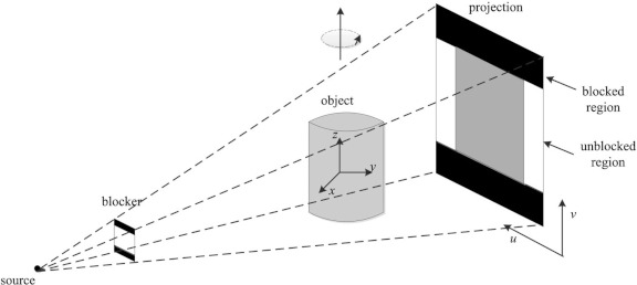
Figure 1 illustrates the experimental setup for scatter measurement and correction. Instead of alternating lead strips which are used in various scatter correction schemes,8 the lead strips are only attached to the two boundaries of the detector along v-direction. This scheme ensures that there exists no loss of image data in the central FOV while concurrently allowing for the collection of the scatter signal on the periphery. A series of projections are acquired with the central unblocked region being the image data, and the two blocked boundaries being scatter measurement, which in turn will be utilized to constrain the proposed compressed sensing retrieval of the scatter.
Figure 1.
Geometry of the experiment setup. The two strips of lead are attached on the periphery of the surface of kV x-ray source of the Varian TrueBeam OBI system. The scatter is detected using the image detectors at the boundaries along the v-direction while the gantry rotates around the z-axis.
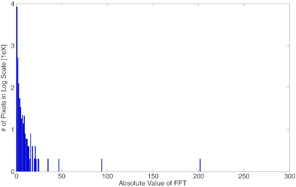
In this work, scatter signal is assumed to be low frequency signal and hence sparse in the corresponding Fourier domain. This assumption is supported by the recent findings10 that demonstrated the low frequency distribution of scatter signals with Monte Carlo (MC) simulations and clinical data. Instead of Fourier transform (FT), we analyze the scatter signal under the discrete cosine transform (DCT) because the DCT operation not only transforms the signal into sparse frequency domain, but also maintains the scatter signal to be real number in both the original space and the transformed space, which facilitates the numerical calculation in successive optimization calculation. Figure 2 illustrates the sparsity of the scatter signal in the two-dimensional DCT (DCT2) domain with the Rando anthropomorphic phantom in half fan mode. A conventional blocker with alternating lead strips was applied to sample the scatter distribution in FOV. The signal in the bracket region is considered as scatter signal and is transformed into the DCT2 domain. The histogram in Fig. 2 illustrates that less than 1.03% of all the entries are greater than 0.1, while more than 95.87% entries are below 0.01.
Figure 2.
The histogram of DCT2 transform of the scatter signal in log scale. Scatter is considered as sparse and low frequency signal as illustrated here that less than 1.03% of all the entries are greater than 0.1, while more than 95.87% entries are below 0.01.
Interpolation method of scatter estimation
To facilitate the following compressed sensing optimization, precomputed scatter estimation is needed as the initial input. The most intuitive and widely used method is the linear interpolation method of the measured scatter signal,3, 8 which reconstructs the scatter signal in unblocked region by interpolating the boundary scatter measurements. The advantages of the linear interpolation method include simple and efficient implementation and accurate estimation when the sampling frequency is high enough. However, the interpolation method may not produce consistently accurate estimation of heterogeneous phantom at undersampled measurement. In our scheme, the large gap between the two edge blocked regions prevents high sampling frequency, and thus the interpolation method may lead to inferior scatter estimation.
Nonlinear kernel model and hybrid model of scatter estimation
Analytical scatter models5, 7, 11 are more robust to inhomogeneity of the object, and those methods mostly involve the assumption that scatter can be modeled into the convolution of a kernel with the projection signal with various considerations. In general the analytical model can be expressed as
| (1) |
where I, P, and S denotes the total signal, the primary signal, and the scatter signal, respectively. k(u, v) is the convolution kernel for the estimation of scatter signal from the primary. Kernel selection is vital in the analytical scatter model, and anisotropic kernels have been demonstrated to be more effective than isotropic ones.7 However, kernel selection complicates the scatter estimation, and more sophisticated kernels may require additional assumptions which may not be always valid in general situations.
To ease the kernel selection process while not losing the patient-specific property, we propose a simple, nonlinear, and projection-based model for regulating the scatter distribution in the FOV area,
| (2) |
where Si, j is desired scatter distribution at pixel (i, j) and Ii, j is the corresponding projection data. a and b are undetermined model parameters which depict the overall magnitude adjustment and local adjustment, respectively. With the interpolated scatter as Si, j, the parameters a and b can be solved using linear regression of log transformed data.
Although the nonlinear scatter model includes the local variation in scatter modeling, it is inferior to interpolation method at high sampling frequencies. On the other hand, interpolation method produces poor prediction at low sampling frequencies when the object is inhomogeneous. In this work, the scatter estimation is completed by compressed sensing optimization, and the algorithm needs a starting point. To facilitate the following compressed sensing optimization by taking the advantages of both interpolation (low frequency signal) and nonlinear kernel methods (high frequency and patient specific information), we propose a hybrid model to compute the initial scatter estimation:
| (3) |
where Si is the interpolation model and Sm is the designed convolution method in Eq. 2. β is a weighting factor which depends on the sampling frequency of interpolation method. In this work,
| (4) |
where Ngap = Nb1 − Nb2 is the unblocked distance in the vertical direction in unit of pixels, and Nv is the total number of pixels along the vertical direction. β approaches zero if Ngap goes to zero, indicating the scatter model Sh goes to the interpolation model when the sampling frequency is very high. When Ngap is large, β approaches one, and Sh goes to the convolution model. Note that the function of the hybrid model is to provide a better starting point for the successive compressed sensing optimization, and its reconstruction does not directly enhance the scatter artifacts from the image.
Compressed sensing optimization of scatter estimation
Recent development of the compressed sensing theory has demonstrated that sparse signal or signal which is sparse in certain domain can be accurately reconstructed from highly undersampled measurements via the L1 norm penalization of the sparse domain of transformed signal. Several algorithms based on the compressed sensing theory has been proposed for CT image reconstruction and treatment planning.17, 18 In this work, the scatter map reconstruction for each projection is formulated as a constrained optimization problem under the framework of compressed sensing theory,
| (5) |
where x is the desired scatter map and its size is the same as the projection size. Sh is the precomputed hybrid model of scatter. Σ is the covariance matrix of x and λ is a weighting factor. DCT2 represents the 2D discrete cosine transform operator.
The first term in the objective is the data fidelity term, which regulates the estimated scatter to be close to the proposed hybrid model. Since the x-ray detection can be modeled as Poisson process, the variance of x equals to its mean. Assume the correlation of x with different indices is negligible, Σ can be formulated into a diagonal matrix as Σ = diag(Sh) with its diagonal terms to be Sh. Therefore,
| (6) |
The second term is the L1 penalty term, which penalizes on high frequency values of x. The DCT2 operator can be written as
| (7) |
where
| (8) |
M and N delineate the numbers of pixels in the rows and columns, respectively. DCT2 can be implemented equivalently by successive 1D DCT operations across the rows and columns. The 1D and 2D DCT operations can be written into matrix multiplication form as
| (9) |
where W1 and W2 are the equivalent 1D DCT columnwise and rowwise operations, and W represents the 2D DCT operation.
The setting of the weighting factor represents the tradeoff between the data fidelity term and the L1 penalty term. Generally, larger λ value represents smoother scatter distribution, and smaller λ value fit the scatter estimation closer to the precomputed hybrid model Sh. In this study, we find λ = 0.01 tends to optimize the solution in terms of mean square error. The proposed λvalue can vary among different separations of width or different machines within a small range, but the same value was applied to the two different phantoms in this study. More optimization of the λ value or pixilated penalty setting can be investigated as further topics.
Therefore, the optimization problem can be written as
| (10) |
The above constraint optimization is called L1 analysis problem, and it is a challenging problem because the 2D DCT operation complicates the variables. Additionally, the size of the variable x is usually too big for many solvers. For instance, there will be nearly 100 000 variables even if the detector size is downsampled to 512 × 200. The solution to this type of problem has been the subject of substantial research; the two main streams of solutions can be categorized as TFOCS (templates for first-order conic solvers) by Candes et al.19 and ADMM (alternating direction method of multipliers) by Boyd et al.20 These methods effectively minimize the objective function and utilize soft-thresholding technique for L1 minimizations. In this work, ADMM is adopted and the detail of the solver is described in the Appendix.
Scatter correction procedure
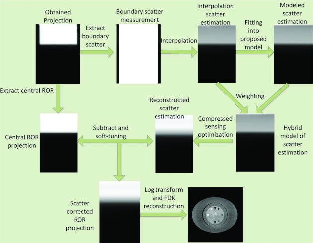
To summarize, the detailed scatter correction procedure is illustrated in Fig. 3.
Figure 3.
Flow chart of the proposed scatter correction procedures: (1) The peripheral scatter measurement is extracted from each projection data and the scatter profiles are used to determine the scatter for central ROR; (2) Bilinear interpolation of the boundary scatter data provides initial estimation of the scatter Si; (3) Least square minimization with the log transform data is applied to find the coefficients a and b in Eq. 2; (4) The hybrid model Sh is computed based on the weighting factor λ; (5) An L1-analysis compressed sensing optimization with positivity constraint is formulated based on the low-frequency assumption of the scatter signal, and it is solved by using ADMM; (6) Estimated scatter is subtracted from the original projection data with soft-thresholding method; and (7) Conventional FDK algorithm is used to reconstruct the scatter corrected image.
Evaluation
FDK reconstructions without scatter correction, with interpolation scatter correction method, and with the proposed scatter correction method were evaluated qualitatively and quantitatively using Catphan©504 and Rando anthropomorphic phantoms. The Catphan©504 phantom was used with an added elliptical body annulus cover to properly model the scatter in thicker regions of body. Both phantoms were aligned with three orthogonal laser points, with their superior/inferior direction along the longitudinal direction of the couch. Projections were obtained from a 360° scan using the Varian TrueBeam STx OBI (Varian Medical System, Inc., Palo Alto) under half fan mode. The x-ray tube was operated at 120 kVp and 80 mA with the pulse width at each projection angle of 20 ms. We collected 656 projections in a single scan with each projection of 1024 × 768 pixels and pixel size of 0.388 × 0.388 mm2. The projections were first downsampled by two to facilitate the successive processing and reconstruction. The reconstructed volume size is of 512 × 512 × 40, and the voxel size is 0.776 × 0.776 × 1.552 mm3. For comparisons of the Catphan©504 reconstruction images, a scatter free image was acquired as the benchmark by an 8 row fan-beam scanner (Discovery ST, GE Medical Systems) with the body annulus removed. The image size is 512 × 512 with pixel size of 0.977 × 0.977 mm2. X-ray tube was set at 120 kVp, 80 mA, and 12 ms pulse width. All reconstructed images of these phantoms used same conversion to Hounsfield unit (HU) for quantitative evaluation.
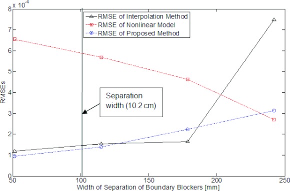
The thickness of each boundary blocker was approximately 3 mm, which resulted in over 99% attenuation of the primary x-ray. The width of the central unblocked region was adjustable according to the size of FOV, and it was set to 3 cm in the phantom studies, and the width of separation in the corresponding image was 10.2 cm. Note the width of separation can be extended to accommodate the size of object.
To quantitatively evaluate the effectiveness of the proposed method, contrast-to-noise ratio (CNR) at selected regions of interest (ROIs) in the reconstructed image was used. The CNR can be calculated as
| (11) |
where and are the means of signal of ROIs and their periphery regions, while σn is the associated standard deviation of noise level in the image.
Another assessment, the accuracy of CT numbers in the ROIs was to compute the root mean square error (RMSE),
| (12) |
where Vi, j is the ith voxel value in HU unit in the jth ROI, and is the associated benchmark value from the MDCT reconstruction. Nj is the number of voxels in the jth ROI. Note that the RMSE analysis is also done in projection space to evaluate the accuracy of the estimated scatter using scatter measurement as the benchmark.
A third gauge is to measure the nonuniformity caused by scatter artifacts in the reconstructed image for the Rando phantom. Spatial nonuniformity (SNU) is defined similar as in Ref. 21,
| (13) |
where and are the maximum and minimum of the mean CT numbers in selected regions, respectively.
RESULTS
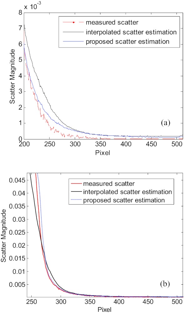
Figure 4 demonstrates the accuracy of the scatter map reconstruction by using the proposed method on the Catphan©504 phantom and the Rando phantom. Here, conventional blocker with alternating strips is used to acquire the ground truth of scatter signal, and our edge blocker with 242 mm gap is used to measure the periphery signal for reconstruction of scatter in the central regions. The corresponding 1D scatter profiles, estimated using the interpolation method and the proposed method with the boundary scatter measurements, are presented in Fig. 4. In both phantom studies, the interpolation scatter estimation and the proposed scatter estimation are close to the measure scatter signal, while the latter outperforms in both phantom studies.
Figure 4.
1D profiles of scatter signals of Catphan©504 phantom (a) and the Rando phantom (b) with ground truth, the interpolation scatter estimation and the proposed scatter estimation.
To further quantitatively illustrate the effect of the distance between the boundaries between edge blockers, pairs of blockers with increased widths of separation are selected, which are 51 mm, 114 mm, 178 mm, and 242 mm, respectively. Figure 5 plots the RMSEs of reconstructed scatter from different methods with increased width of separation with the measurement as the ground truth. As shown in the figure, the RMSE of the interpolation methods increases along the width of separation, and it jumps to very high level when the distance reaches over 200 mm, which demonstrates unstable reconstruction of the scatters signal. The RMSE of nonlinear model on the other hand, decreases along the width of separation, but it exceeds those of other methods within 200 mm distance. The RMSE of proposed method is more stable compared with the other two methods, and generally at a lower level of RMSE over all separation widths. Note that the nonlinear model and the hybrid model may represent a lower value at certain width of separation, but their reconstructed images are inferior to the proposed method.
Figure 5.
RMSEs of scatter estimate as a function of blocker separation width. The vertical line in the plot indicates the separation width used in our image quality study.
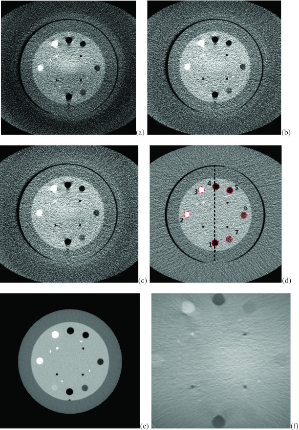
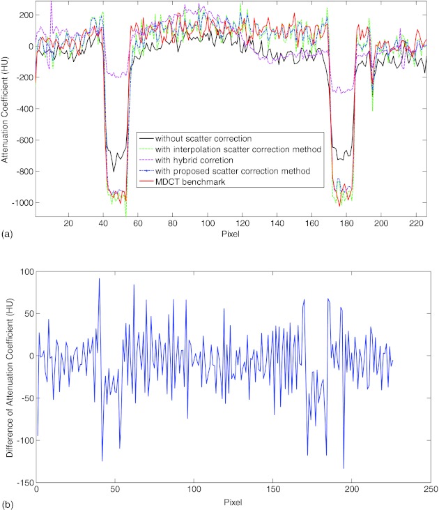
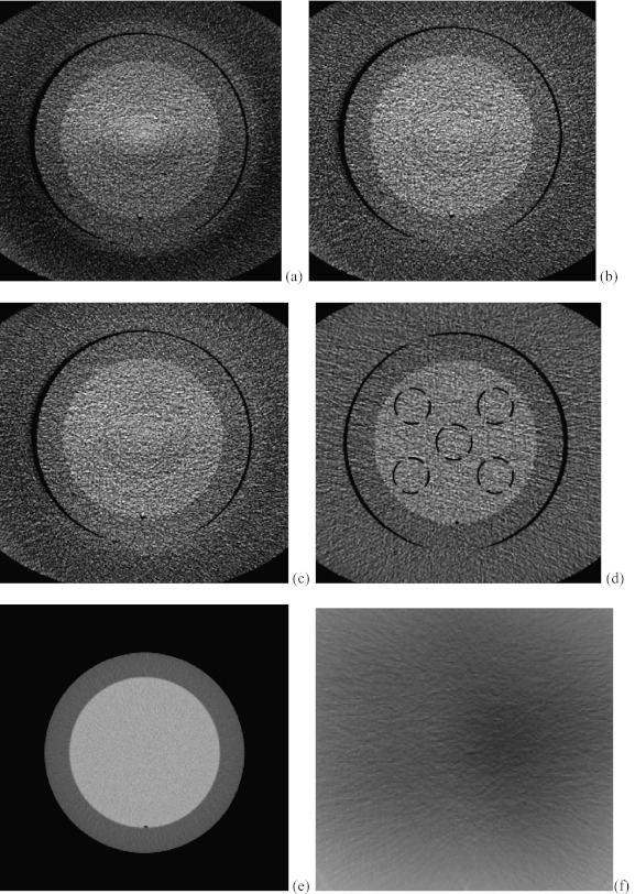
Figure 6 shows the axial slices from the CBCT reconstructions with no scatter correction, the interpolation correction method and the proposed method. The reconstructed slice with fan beam MDCT is also provided in Fig. 6d with annulus cover and Fig. 6e without the cover as the benchmark. Figure 6a shows the image reconstructed using FDK algorithm without scatter correction. Scatter artifacts are observed within the ambient elliptical body annulus cover area as well as in the central area. The scatter artifacts are mitigated by using the interpolation scatter correction method in Fig. 6b. Reduced scatter artifacts and improved image quality is also obtained in Fig. 6c by using the proposed method. Note in the following comparison, the Catphan phantom with annulus cover is used because it represents the same phantom as different correction methods. Figure 6f provides the difference image between Figs. 6b, 6c. To compare the reconstructed images quantitatively, 1D profiles marked in the corresponding positions of images in Fig. 6 are plotted into Fig. 7. Figure 7 reveals that the interpolation scatter correction method and the proposed scatter correction achieved similar profiles, which are close to the benchmark signal. On the other hand, 1D profile without scatter correction applied deviates from the benchmark heavily. Note that the hybrid model reconstruction results deviates from the benchmark heavily, which indicates that its purpose is to facilitate the compressed sensing optimization rather than to provide a directly solution, and therefore, we cease comparing the hybrid model results in the following sessions.
Figure 6.
The corresponding axial slices of Catphan©504 phantom from CBCT reconstructions. Image window: [−180 220]. (a) FDK reconstruction without scatter correction; (b) FDK reconstruction with interpolation scatter correction method; (c) FDK reconstruction with the proposed scatter correction method; (d) reconstructed slice with fan beam MDCT with annulus cover; (e) reconstructed slice with fan beam MDCT without annulus cover; (f) the difference image between (b) and (c).
Figure 7.
(a) 1D profiles from the corresponding reconstructed slices without scatter correction, with interpolation scatter correction method, with proposed scatter correction method and the MDCT benchmark. (b) The difference of 1D profiles between the interpolation method and the proposed scatter correction method.
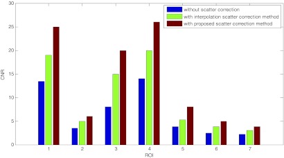
The CNRs for the seven selected ROIs in the reconstructed images are plotted into Fig. 8. The proposed scatter correction method improved the CNRs about twofolded, while leverage of CNRs by the interpolation scatter correction method is inferior to the proposed method. To further compare the reconstruction results, the CT numbers for the selected ROI are collected in Table 1. Compared with the slice from MDCT without annulus cover, CT numbers for ROIs in the image without scatter correction deviates from the benchmark especially at ROIs with very high or low CT numbers, which also indicates the reason of the damaged image contrast. The CT numbers of images with interpolation and proposed scatter correction are demonstrated to be close to the MDCT benchmark. The RMSE for these selected ROIs with the proposed scatter correction methods is about ten times smaller than that for images without scatter correction.
Figure 8.
The CNRs for the seven selected ROIs from the reconstructed images without scatter correction, with the interpolation scatter correction method, and with the proposed scatter correction method.
Table 1.
Comparison CT numbers for the selected ROIs with different methods.
| ROI | Material | MDCT without annulus cover | Without scatter correction | With interpolation method | With proposed method |
|---|---|---|---|---|---|
| 1 | Air | −970 | −806 | −933 | −967 |
| 2 | DelrinTM | 340 | 268 | 350 | 346 |
| 3 | Teflon | 927 | 673 | 924 | 920 |
| 4 | Air | −968 | −820 | −998 | −996 |
| 5 | PMP | −177 | −169 | −193 | −196 |
| 6 | LDPE | −86 | −90 | −82 | −85 |
| 7 | Polystyrene | −25 | −57 | −20 | −30 |
| RMSE | 130 | 19 | 13 |
Figure 9 shows another set of corresponding axial slices from CBCT reconstructions. RMSE analysis of the mean value of CT numbers in the dash circled areas in Fig. 9 was performed against the benchmark of MDCT image with (d) and without annulus cover (e). In Fig. 9a, the RMSE of the mean CT numbers in the selected areas is 33.7. In Fig. 9b, the RMSE of the image with the proposed scatter correction method drops to 18.1, nearly 53% of the previous RMSE. In Fig. 9c, the RMSE of the mean CT number in the circled region between image with interpolation scatter correction and the benchmark is about 22.6. Figure 9f provides the difference image between Figs. 9b, 9c.
Figure 9.
Another set of corresponding axial slices of Catphan©504 phantom from CBCT reconstructions. Image window: [−170 230]. (a) FDK reconstruction without scatter correction; (b) FDK reconstruction with interpolation scatter correction method; (c) FDK reconstruction with the proposed scatter correction method; (d) reconstructed slice with fan beam MDCT with annulus cover; (e) reconstructed slice with fan beam MDCT without annulus cover; (f) difference image between image (b) and (c).
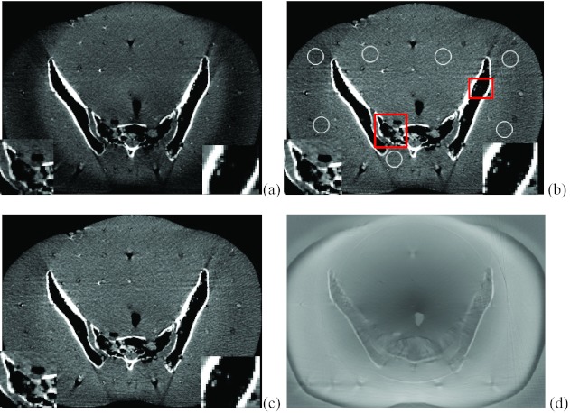
Figure 10 demonstrates the reconstructed slices of the Rando phantom with no scatter correction, with the interpolation scatter correction method and the proposed scatter correction method. The image window is set to [−250 230]. By visual observation, the image without correction is contaminated with scatter artifacts, resulting in the dark region in the boundary and nonuniform image effect. The interpolation scatter correction mitigates the darkness and the nonuniformity of the image, while the proposed method further corrects the scatter artifacts. The insets in each reconstructed slice demonstrate that the proposed method provides better detailed resolution. The SNU of the selected regions [circled in Fig. 10a] for the image without scatter correction is 10.9%. With the interpolation scatter correction, the SNU for Fig. 10b drops to 8.3%. The SNU further decreases to 6.8% for the image with the proposed scatter correction. Figure 10f provides the difference image between Figs. 10b, 10c.
Figure 10.
Axial slices of Rando phantom from CBCT reconstructions. Image window: [−230 250]. (a) FDK reconstruction without scatter correction; (b) FDK reconstruction with interpolation scatter correction method; (c) FDK reconstruction with the proposed scatter correction method. The insets in the squared areas demonstrated better resolution of the proposed method; (d) the difference image between image (b) and (c).
DISCUSSION AND CONCLUSION
Blocker-based scatter correction techniques have several desired features that are suitable for clinical applications, including high scatter estimation accuracy and no need for prior knowledge of the imaging object. However, the existing blocker-based scatter correction methods require either elongated machine time for extra scans, or a moving blocker during the scan. Specific designed blocker or scatter correction schemes can complete the acquisition of the primary and scatter data within one scan, but such schemes are only applicable to certain machine acquisition mode. An effective image acquisition and reconstruction algorithm for scatter correction in has been described in this paper. The advantages of proposed method are fourfolded: (1) stationary boundary scatter measurement scheme enables the image acquisition and scatter measurement into a single scan; (2) a compressed sensing technique with the ADMM method solves the scatter estimation efficiently, which indicates that our method is readily to translate into software packages for CT systems; (3) the periphery scatter detection avoids obstructing the FOV and degrading the primary signal as in the general blocker methods, and leads to a more practical approach that ensures high quality reconstruction of the image data; (4) finally, the scatter correction scheme is suitable for both full fan mode and half fan mode, so it is readily translatable into different commercial machines.
The performance of the proposed method has been evaluated using phantoms on the Varian TrueBeam CBCT system. In this work, the lead strips were manually designed and attached between the x-ray source and the object for higher attenuation, where the blades in the system can be designed and utilized in the future. Nevertheless, the reconstructed images indicate that the proposed scatter correction method improved the image quality and mitigated the scatter artifacts. The RMSE of the proposed method for ROIs in the Catphan©504 phantom was dramatically reduced to 10% of that without scatter correction. The CNR of the proposed method on Catphan©504 phantom was also leveraged to about twice of that without scatter correction. SNU measurement for the Rando phantom also indicates better uniformity of the results with the proposed method. The widely used interpolation scatter correction method was also included into the comparison of results, and its performance was found to slightly inferior to the proposed method.
The separation width is determined by the FOV and scatter measurement requirement. Within required FOV, the separation width can be set as large as possible if scatter at the shade of the object can be measured. The proposed method can handle large FOV scatter estimation thanks to the compressed sensing technique.
The efficiency of the proposed scatter correction algorithm cannot be ignored, since the compressed sensing optimization converges quickly within tens of steps and each iteration step is implemented fast. With our single PC equipped with 4G memory and Intel® Core 2 Duo CPU, the correction for each projection finish within about 20 s in MATLAB. Higher efficiency is expected with more sophisticated programming consideration. For better clinical application of the proposed scatter correction method, more consideration and discussion need to be made here. (1) The proposed scatter correction method largely depends on the precomputed scatter model, which is a weighted combination of interpolation and kernel method in this work. Investigation of more precise and easily computable models is of great interest in our future research. (2) Based on the low frequency assumption of the scatter signal, the compressed sensing optimization in this work penalized on the L1 norm of the discrete cosine transform of each projection individually. In reality, the scatters between different projections are correlated, such as the neighbor views or the opposite views are highly correlated. Therefore, joint estimation of the scatter among all projections seems to produce better scatter correction schemes. (3) As a common problem for most scatter correction method, the noise signal level is increased slightly in the reconstructed image. Noise suppression algorithms22, 23 can be employed in the reconstruction step to further improve the image quality.
In conclusion, a single-scan image acquisition and scatter correction method is proposed and validated by using stationary edge detection and compressed sensing technique. The proposed method was demonstrated to effectively reduce the scatter artifacts and improve the image quality without using prior images, multiscans or moving blockers. The compressed sensing optimization can be executed efficiently and the experiment setup of the blocker can be applied across different CT systems with both half fan and full fan mode.
ACKNOWLEDGMENT
This project was supported in part by NCI (Grant No. 1R01 CA133474) and NSF (Grant No. 0854492).
APPENDIX: ALTERNATING DIRECTION METHOD OF MULTIPLIERS TO SOLVE THE CONSTRAINED OPTIMIZATION
The L1 analysis problem in Eq. 10 is
| (A1) |
The algorithm for solving Eq. A1 can be written as
| xk + 1 = (xk + 1)+ |
To solve the first step, we can write it as
| (A2) |
We can add a smoothing term into the objective while not changing it,
| (A3) |
The dual problem can be written as
| (A4) |
With ADMM method, this can be solved iteratively by the following algorithm:
| yk + 1 = yk + ρ(WTxk − zk) |
where the soft-thresholding function is defined as
| (A5) |
Since WTW = I is an identity matrix, and Σ−1 is also diagonal, the whole algorithm can be updated very fast. The convergence is also guaranteed within tens of steps with proper setting of the parameters. In this paper, we tested and set λ = 0.01 and ρ = 0.1.
References
- Rybicki F. J., Otero H. J., Steigner M. L., Vorobiof G., Nallamshetty L., Mitsouras D., Ersoy H., Mather R. T., Judy P. F., Cai T., Coyner K., Schultz K., Whitmore A. G., and Carli M. F. D., “Initial evaluation of coronary images from 320-detector row computed tomography,” Int. J. Cardiovasc. Imaging 24, 535–546 (2008). 10.1007/s10554-008-9308-2 [DOI] [PubMed] [Google Scholar]
- Siewerdsen J. H., Moseley D. J., Bakhtiar B., Richard S., and Jaffray D. A., “The influence of antiscatter grids on soft-tissue detectability in cone-beam computed tomography with flat-panel detectors,” Med. Phys. 31, 3506–3520 (2004). 10.1118/1.1819789 [DOI] [PubMed] [Google Scholar]
- Siewerdsen J. H., Daly M. J., Bakhtiar B., Moseley D. J., Richard S., Keller H., and Jaffray D. A., “A simple, direct method for x-ray scatter estimation, and correction in digital radiography, and cone-beam CT,” Med. Phys. 33, 187–197 (2006). 10.1118/1.2148916 [DOI] [PubMed] [Google Scholar]
- Lee H., Xing L., Lee R., and Fahimian B. P., “Scatter correction in cone-beam CT via a half beam blocker technique allowing simultaneous acquisition of scatter, and image information,” Med. Phys. 39, 2386–2396 (2012). 10.1118/1.3691901 [DOI] [PubMed] [Google Scholar]
- Boone J. M. and Seibert J. A., “An analytical model of the scattered radiation distribution in diagnostic radiology,” Med. Phys. 15, 721–725 (1988). 10.1118/1.596186 [DOI] [PubMed] [Google Scholar]
- Jin J.-Y., Ren L., Kim J., Wen N., Movsas B., Chetty I. J., Liu Q., and Guan H., “Combining scatter reduction and correction to improve image quality in cone-beam computed tomography (CBCT),” Med. Phys. 37, 5634–5644 (2010). 10.1118/1.3497272 [DOI] [PubMed] [Google Scholar]
- Sun M. and Star-Lack J. M., “Improved scatter correction using adaptive scatter kernel superposition,” Phys. Med. Biol. 55, 6695–6720 (2010). 10.1088/0031-9155/55/22/007 [DOI] [PubMed] [Google Scholar]
- Zhu L., Xie Y., Wang J., and Xing L., “Scatter correction for cone beam CT in radiation therapy,” Med. Phys. 36, 2258–2268 (2009). 10.1118/1.3130047 [DOI] [PMC free article] [PubMed] [Google Scholar]
- Wang J., Mao W., and Solberg T., “Scatter correction for cone-beam computed tomography using moving blocker strips: A preliminary study,” Med. Phys. 37, 5792–5801 (2010). 10.1118/1.3495819 [DOI] [PubMed] [Google Scholar]
- Zhu L., Bennett N. R., and Fahrig R., “Scatter correction method for x-ray ct using primary modulation: Theory and preliminary results,” IEEE Trans. Med. Imaging 25, 1573–1587 (2006). 10.1109/TMI.2006.884636 [DOI] [PubMed] [Google Scholar]
- Li H., Mohan R., and Zhu X. R., “Scatter kernel estimation with an edge-spread function method for cone-beam computed tomography imaging,” Phys. Med. Biol. 53, 6729–6748 (2008). 10.1088/0031-9155/53/23/006 [DOI] [PubMed] [Google Scholar]
- Niu T. and Zhu L., “Scatter correction for full-fan volumetric CT using a stationary beam blocker in a single full scan,” Med. Phys. 38, 6027–6038 (2011). 10.1118/1.3651619 [DOI] [PMC free article] [PubMed] [Google Scholar]
- Jarry G., Verhaegen F., Graham S. A., Moseley D. J., Jaffray D. J., and Siewerdsen J. H., “Characterization of scattered radiation in kV CBCT images using Monte Carlo simulations,” Med. Phys. 33, 4320–4329 (2006). 10.1118/1.2358324 [DOI] [PubMed] [Google Scholar]
- Ning R. and Tang X., “X-ray scatter correction algorithm for cone beam CT imaging,” Med. Phys. 31, 1195–1203 (2004). 10.1118/1.1711475 [DOI] [PubMed] [Google Scholar]
- Sorenson J. A. and Floch J., “Scatter rejection by air gaps: An empirical model,” Med. Phys. 12, 308–316 (1985). 10.1118/1.595690 [DOI] [PubMed] [Google Scholar]
- Feldkamp L. A., Davis L. C., and Kress J. W., “Practical cone-beam algorithm,” J. Opt. Soc. Am. 1, 612–619 (1984). 10.1364/JOSAA.1.000612 [DOI] [Google Scholar]
- Sidky E. Y. and Pan X., “Image reconstruction in circular cone-beam computed tomography by constrained, total-variation minimization,” Phys. Med. Biol. 53, 4777–4807 (2008). 10.1088/0031-9155/53/17/021 [DOI] [PMC free article] [PubMed] [Google Scholar]
- Meng B., Zhu L., Widrow B., Boyd S., and Xing L., “A unified framework for 3D radiation therapy and IMRT planning: Plan optimization in the beamlet domain by constraining or regularizing the fluence map variations,” Phys. Med. Biol. 52, N521–N531 (2010). 10.1088/0031-9155/55/22/N01 [DOI] [PubMed] [Google Scholar]
- Becker S., Candès E. J., and Grant M., “Templates for convex cone problems with applications to sparse signal recovery,” Math. Program. Comput. 3(3), 165–218 (2011). 10.1007/s12532-011-0029-5 [DOI] [Google Scholar]
- Boyd S., Parikh N., Chu E., Peleato B., and Eckstein J., “Distributed optimization and statistical learning via the alternating direction method of multipliers,” Found. Trends Mach. Learn. 3(1), 1–122 (2011). 10.1561/2200000016 [DOI] [Google Scholar]
- Mail N., Moseley D. J., Siewerdsen J. H., and Jaffray D. A., “The influence of bowtie filtration on cone-beam CT image quality,” Med. Phys. 36, 22–32 (2009). 10.1118/1.3017470 [DOI] [PubMed] [Google Scholar]
- Lubner M. G., Pickhardt P. J., Tang J., and Chen G., “Reduced image noise at low-dose multidetector CT of the abdomen with prior image constrained compressed sensing algorithm,” Radiology 260, 248–256 (2011). 10.1148/radiol.11101380 [DOI] [PubMed] [Google Scholar]
- Zhu L., Wang J., and Xing L., “Noise suppression in scatter correction for cone-beam CT,” Med. Phys. 36, 741–752 (2009). 10.1118/1.3063001 [DOI] [PMC free article] [PubMed] [Google Scholar]


