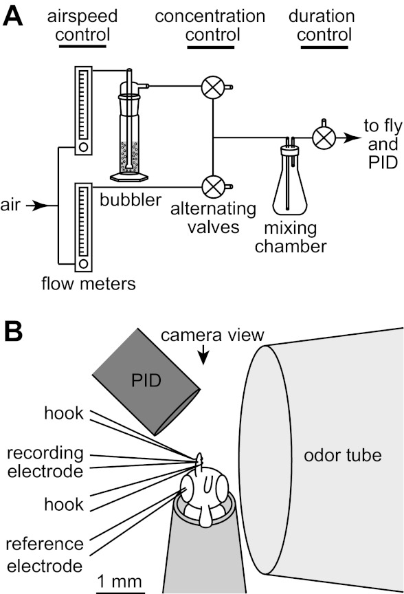
Fig. 2.

Experimental setup. A: schematic of the odor delivery device. Air speed was controlled by changing the flow through 2 matched flowmeters that were set to the same flow rate. The output of 1 flowmeter was sent through a large column of pure liquid odorant, producing saturated (or nearly saturated) vapor. The odorized air stream and its matched clean air stream were each sent to a 3-way valve. These 2 valves were always held in opposite states so that only 1 would be passed to the mixing chamber at any given time while the other was vented. The concentration of the final odor pulse was controlled by altering the duty cycle of switching between the valves. The timing of the final odor pulse was controlled by a valve near the fly. PID, photoionization detector. B: scale diagram of the recording configuration, as seen from above, through the microscope objective. The fly was placed in as close as possible to the odor tube and the PID. A miniature video camera near the fly's head permitted precise positioning of the fly. One antenna was lifted off the fly's head and stabilized with a pair of fine glass hooks. The recording electrode was inserted into a sensillum on this antenna, and the ground electrode was inserted into an eye.
