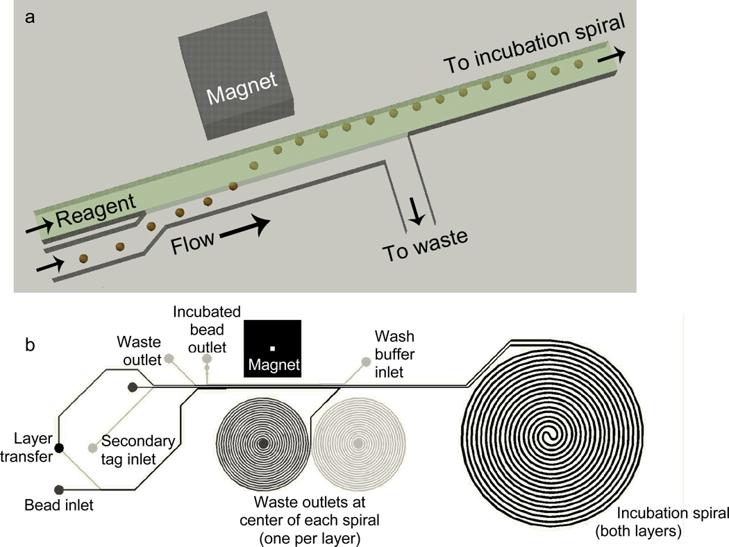
Figure 2.

(a) Schematic of magnetically actuated bead transfer. The magnet pulls the beads from the carrier stream into the reagent stream, and the carrier stream is diverted to waste so that only the reagent stream with the microbeads continues to an incubation spiral. The device uses two of these separation regions on two aligned and bonded device layers, first to transfer the microbeads into the plasma sample, and second to transfer them into the fluorescently labeled secondary antibody. (b) CAD drawing showing the entire microfluidic channel layout. Black lines are on the upper layer and gray lines are on the lower layer. The large spiral (incubation spiral) is identical on both layers. The smaller spirals are incorporated only to balance hydrodynamic resistance for flow control.
